
Low power consumption and high pressure resistant proportionality electromagnet

A proportional electromagnet, high-voltage technology, applied in the direction of electromagnet with armature, electromagnet, circuit, etc., can solve the problems of small output force/current, unfavorable stable operation, coil temperature rise, etc., to improve the output force/current ratio, improve the working stability, the effect of low temperature rise of the coil

Inactive Publication Date: 2009-05-27
ZHEJIANG UNIV +1
View PDF3 Cites 17 Cited by
  • Summary
  • Abstract
  • Description
  • Claims
  • Application Information

AI Technical Summary

Problems solved by technology

[0003] However, the proportional electromagnet disclosed above has the disadvantage of relatively small output force / current, and the power consumption is relatively large when driving a large load, so that the coil temperature rises, which is not conducive to long-term stable work.

Method used


Image

  • Low power consumption and high pressure resistant proportionality electromagnet
  • Low power consumption and high pressure resistant proportionality electromagnet
  • Low power consumption and high pressure resistant proportionality electromagnet

Examples


Embodiment Construction

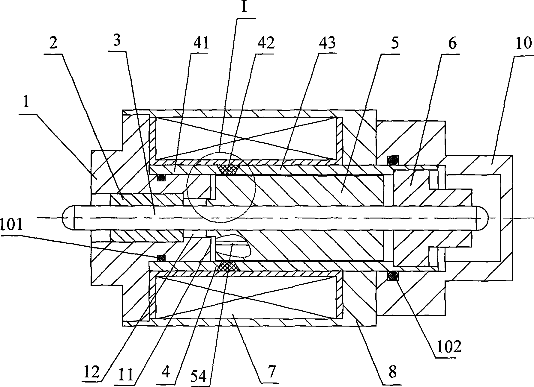
[0037] Figure 1 ~ Figure 2 In combination, a low-power consumption and high-voltage resistant proportional electromagnet is provided, which includes a housing 8 with a rectangular parallelepiped shape and a cylindrical inner hole and a cylindrical guide sleeve 4 with a cylindrical shape and a cylindrical inner hole (that is, the guide The cross-section at any place of the cover 4 is the circular ring of the same size); the guide cover 4 is located in the housing 8, and the control coil 7 is set between the guide cover 4 and the housing 8, and the control coil 7 can be selected as a concentric spiral Tubular control coil.

[0038] An armature 5 slidingly connected with the guide sleeve 4 is provided in the inner cavity of the guide sleeve 4 .

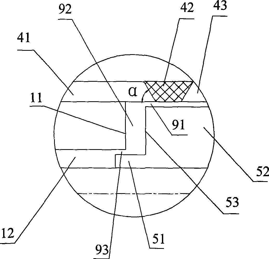
[0039] The guide sleeve 4 is composed of the front section 41, the middle section 42 and the back section 43 which are connected in sequence. In order to obtain good output characteristics, the taper angle α should be controlled at 55...


PUM


Abstract

The present invention discloses a low power consumption high pressure resistant proportional electromagnet which comprises the following steps: setting a guide sleeve inside a shell, and a control coil between guide sleeve and the shell; setting a armature inside inner cavity of guide sleeve wherein the guide sleeve comprising a forepart, a middle part and a rear part, left cover connects with forepart, and end surface of left cover inside inner cavity of forepart; seal connecting right cover with rear part; composing armature with large cylinder and small cylinder; connecting right end of a push rod with right bearing, left end with left bearing, push rod with armature; locating part of the small cylinder inside cover hole of left cover; forming radial working air gap I by gap between inner cavity surface of forepart and large cylinder outer surface; forming radial working air gap II by gap between hole wall of cover hole and outer surface of small cylinder; and forming radial working air gap by gap between interface of small cylinder and large cylinder and end surface. The low power consumption high pressure resistant proportional electromagnet described in the invention can reduce system energy consumption.

Description

technical field [0001] The invention relates to an electro-mechanical conversion mechanism for a proportional valve in a fluid control system, in particular to a low-power-consumption and high-pressure-resistant proportional electromagnet. Background technique [0002] Proportional electromagnet is an electric-mechanical conversion device of electro-hydraulic proportional control element, and its function is to convert the current signal output by the proportional control amplifier into force or displacement. Patent DE3309904 discloses a proportional electromagnet with a typical pot-type pole shoe structure, which has a simple structure and mature technology, and is widely used in electro-hydraulic proportional valves. Patents UA75780 and SU1207318 respectively disclose a proportional electromagnet with a special armature end face shape, which improves the electromagnetic force level characteristics. Patent CN1414251 discloses a proportional electromagnet with a stepped arm...

Claims


Application Information

Patent Timeline
IPC IPC(8): H01F7/08H01F7/123
Inventor 李勇丁凡翁振涛崔剑
Owner ZHEJIANG UNIV
Learn More