Electrostatic protection structure for low trigger voltage thyristor

A low trigger voltage, electrostatic protection technology, applied in circuits, electrical components, electrical solid devices, etc., can solve the problem of high reverse breakdown voltage, achieve the effect of large current gain, convenient design, and improve electrostatic discharge capacity

Active Publication Date: 2009-05-27
SHANGHAI HUAHONG GRACE SEMICON MFG CORP
View PDF0 Cites 5 Cited by
  • Summary
  • Abstract
  • Description
  • Claims
  • Application Information

AI Technical Summary

Problems solved by technology

Usually the reverse breakdown voltage of the NW/PW junction is rela

Method used


Image

  • Electrostatic protection structure for low trigger voltage thyristor
  • Electrostatic protection structure for low trigger voltage thyristor
  • Electrostatic protection structure for low trigger voltage thyristor

Examples


Embodiment Construction

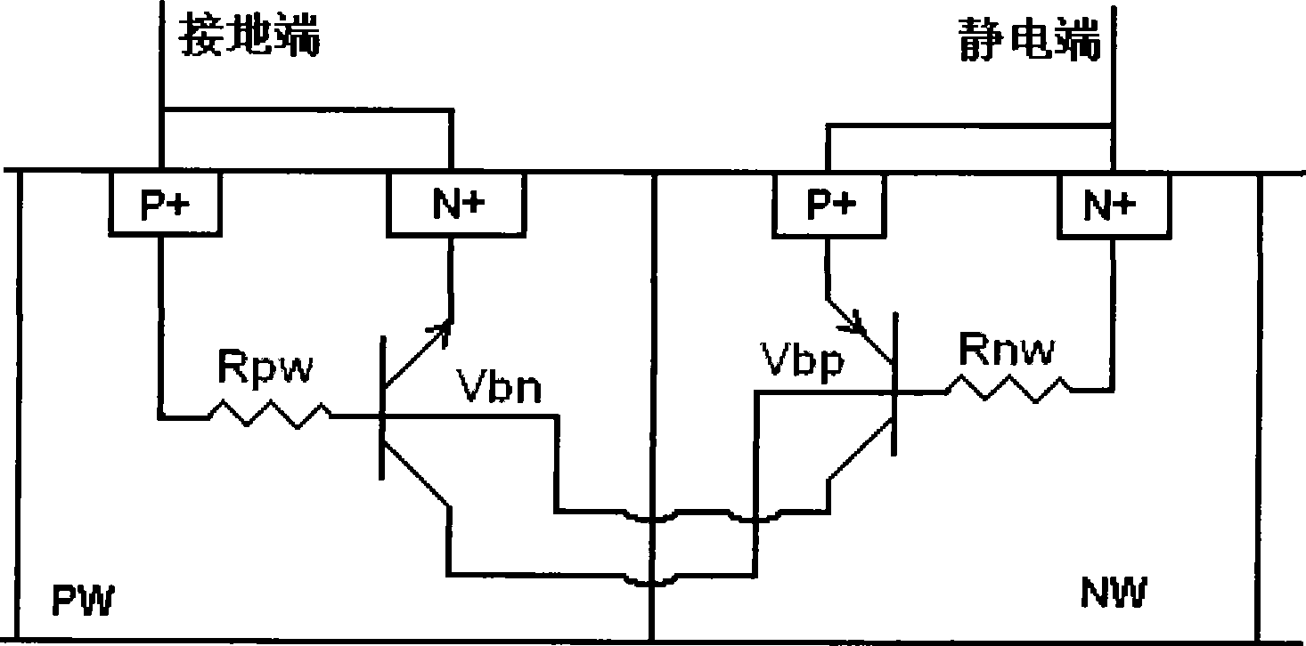
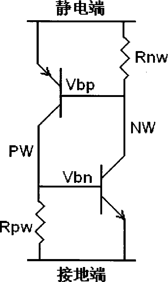
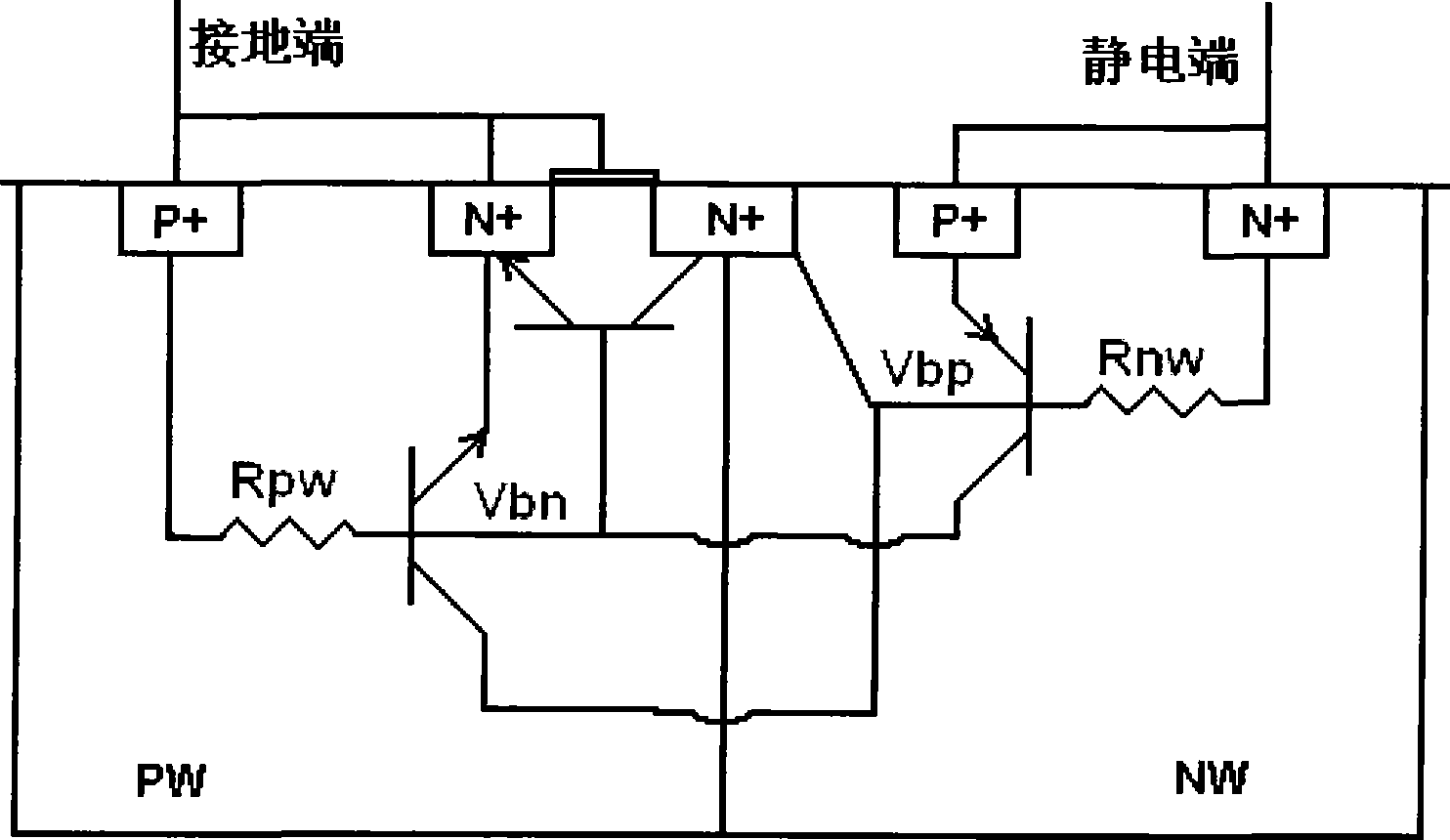
[0020] Such as Figure 5 As shown, due to the parasitic NPN transistor formed by N+ / PW / N+ and the NPN transistor formed by parasitic N+ / PW / NW have the same emitter and base, when the NPN transistor formed by N+ / PW / N+ When the tube is turned on, the NPN formed by the parasitic N+ / PW / NW is also turned on at the same time, thus triggering the SCR composed of the parasitic PNP tube formed by P+ / NW / PW and the NPN tube formed by N+ / PW / NW structure. Figure 6 yes Figure 5 The equivalent circuit diagram.

[0021] As shown in the figure, the low trigger voltage thyristor electrostatic protection structure of the present invention includes:

[0022] An NMOS transistor is formed in the PW (P well); the parasitic NPN transistor formed by N+ / PW / N+ of the NMOS transistor has the same emitter and base as the NPN transistor formed by the parasitic N+ / PW / NW. The drain terminal of the NMOS transistor is electrically connected to the electrostatic terminal through the NW resistor Rnwl, and ...


PUM


Abstract

The invention discloses a low-trigger voltage thyristor static protective structure, which comprises an NMOS transistor and an SCR structure, wherein the NMOS transistor is formed in PW; an NPN transistor formed by N+/PW/N+ parasitized by the NMOS transistor and an NPN transistor formed by parasitic N+/PW/NW have the same emitter terminal and base terminal; the SCR structure consists of a parasitic PNP transistor formed by N+/PW/NW and a parasitic NPN transistor formed by N+/PW/NW; a drain electrode of the NMOS transistor is in electrical connection with the static terminal through an NW resistor Rnw1; and trigger of the SCR structure is controlled by the NMOS transistor and the NW resistor Rnw1. The low-trigger voltage thyristor static protective structure can effectively reduce trigger voltage during SCR static protection, and can adjust the trigger voltage according to requirement so as to greatly facilitate static protection design, and can adjust current gain of the SCR structure according to requirement, thereby improving the static protecting capability of the structure.

Description

technical field [0001] The invention designs an electrostatic protection device structure, in particular relates to an electrostatic protection structure for a low trigger voltage thyristor. Background technique [0002] As an electrostatic protection device, a thyristor (SCR) has a stronger electrostatic discharge capability than a metal-oxide-semiconductor field effect transistor (MOSFE). Generally, the electrostatic discharge capability of an SCR structure is 5 to 7 times that of a MOSFET. figure 1 Shown is a schematic cross-sectional structure diagram of a high trigger voltage SCR structure. exist figure 1 Among them, the collector of the parasitic PNP transistor formed by P+ / NW / PW is also the base of the parasitic NPN transistor formed by N+ / PW / NW; similarly, the collector of the parasitic NPN transistor formed by N+ / PW / NW is also P+ / NW The base of the parasitic PNP tube formed by / PW. figure 1 The equivalent circuit diagram composed of parasitic NPN and PNP tubes in...

Claims


Application Information

Patent Timeline
IPC IPC(8): H01L27/02H01L23/60
CPCH01L2924/0002
Inventor 田光春
Owner SHANGHAI HUAHONG GRACE SEMICON MFG CORP
Why Eureka
Try Eureka