
Three-phase/biphase coordinates conversion method for frequency changer

A technology of coordinate transformation and frequency converter, which is applied in the direction of output power conversion device, AC power input conversion to AC power output, electrical components, etc., can solve the problems of high cost, high real-time processing capacity requirements, high technical difficulty, etc., to achieve Save resources, improve real-time processing capabilities, and improve response speed

Active Publication Date: 2009-05-27
JIAOZUO HUAFEI ELECTRONIC & ELECTRIC CO LTD
View PDF0 Cites 0 Cited by
  • Summary
  • Abstract
  • Description
  • Claims
  • Application Information

AI Technical Summary

Problems solved by technology

Since the central processing unit DSP needs to process multiple operational tasks in real time through programming, such as the acquisition, calculation, communication, and generation of PWM waves of multiple signals such as power synchronization signals, current signals, and bus voltage signals, it takes up most of the resources of the DSP. Therefore, the inverter has high requirements on the real-time processing capability of DSP, and the improvement of DSP's real-time processing capability usually starts from the performance of DSP itself, such as adding a multi-processing system, but its technical difficulty is very high, and the investment cost is also high.

Method used


Image

  • Three-phase/biphase coordinates conversion method for frequency changer
  • Three-phase/biphase coordinates conversion method for frequency changer
  • Three-phase/biphase coordinates conversion method for frequency changer

Examples


Embodiment Construction

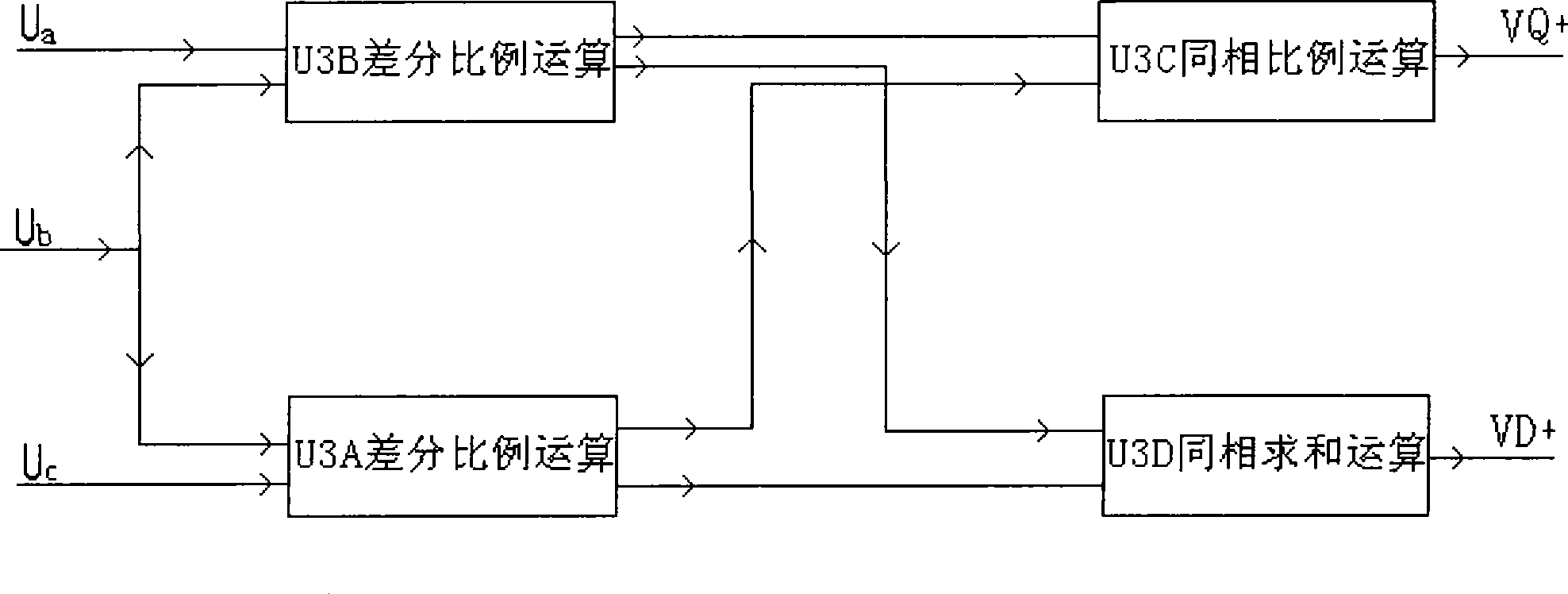
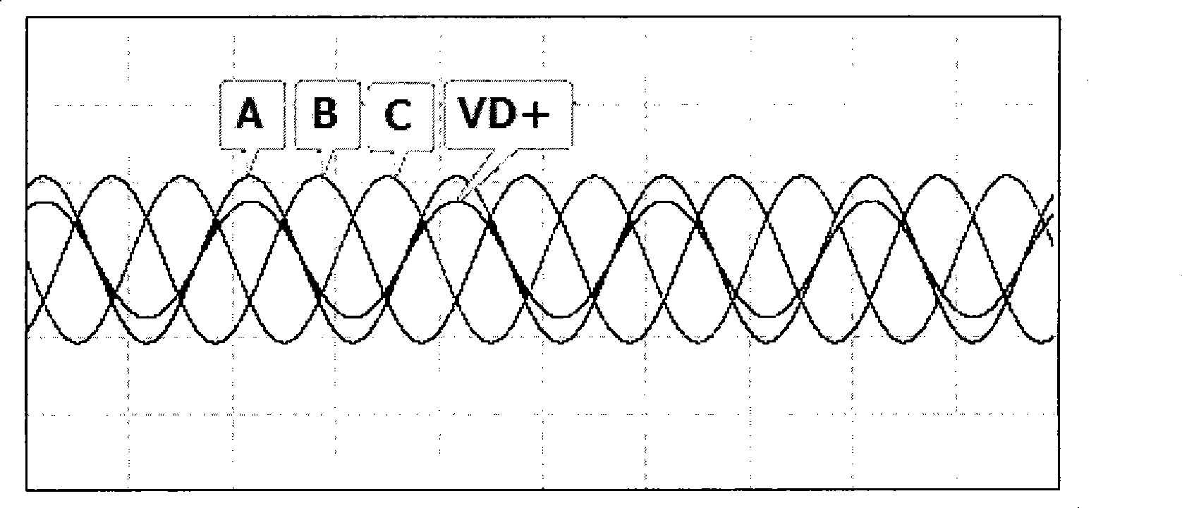
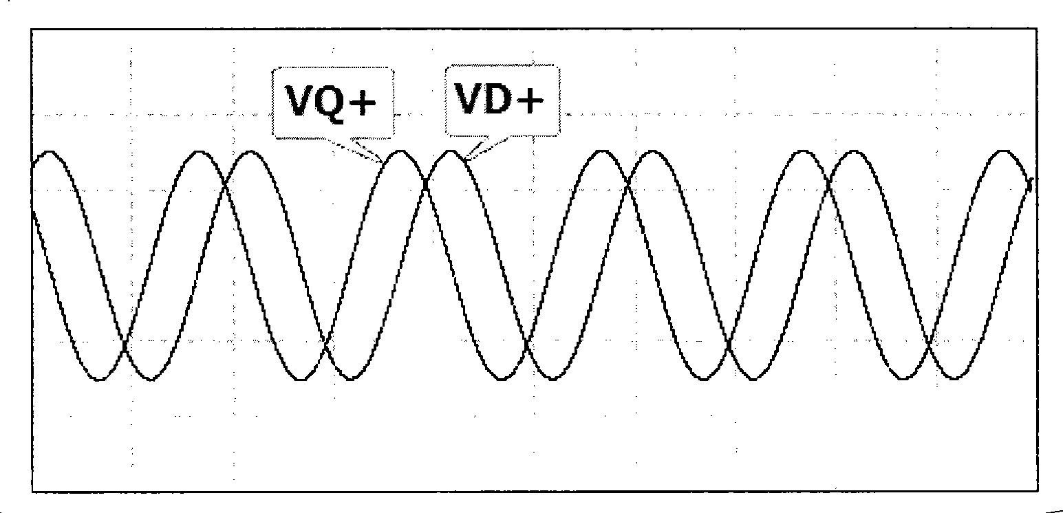
[0014] figure 1 It is a functional block diagram of the three-phase / two-phase coordinate transformation method of the present invention. The three-phase / two-phase coordinate transformation method of the present invention is to adopt the method of differential proportional operation, same-phase proportional operation and same-phase summation operation to complete U under the stationary coordinate system. a , U b , U c The three-phase voltage signal is converted into a voltage signal in the VD+ and VQ+ two-phase static coordinate system. The method is divided into the following steps: Step 1: Put U a u b Two-phase voltage signal and U b u c The two-phase voltage signals are respectively subjected to differential proportional calculations; Step 2: The differential proportional calculation voltage signals completed in Step 1 are respectively subjected to the same-phase proportional calculation and the same-phase sum proportional calculation; Step 3: The voltage signal that...


PUM


Abstract

The invention provides a three-phase / two-phase coordinate conversion method for a frequency converter. The conversion method can convert three phase voltage signals (Ua, Ub, and Uc) under a static coordinate system into two phase voltage signals (VD+ and VQ+) under the static coordinate system by the following steps: step one, two phase voltage signals, namely the Ua and the Ub and two phase voltage signals, namely the Ub and the Uc are subjected to differential proportion operation respectively; step two, the voltage signals which finish the differential proportion operation in step one are subjected to in-phase proportion operation and in-phase summation proportion operation respectively; and step three, the voltage signals which finish an operation result in step two output the two phase voltage signals, namely the VD+ and the VQ+ under the static coordinate system. The method utilizes an electronic circuit to solve the problem that the three phase voltage signals under the static coordinate system are equivalently transformed into the two phase voltage signals under the static coordinate system, saves the resource of a central processing unit, and improves the real-time processing capacity of the central processing unit of the frequency converter.

Description

technical field [0001] The invention relates to a three-phase / two-phase coordinate transformation method, in particular to a three-phase / two-phase coordinate transformation method used on a frequency converter. Background technique [0002] In the industrial inverter technology, the equivalent conversion of the three-phase voltage signal in the static coordinate system to the two-phase voltage signal in the static coordinate system is usually carried out by software. In the frequency converter, the central processing unit DSP is generally used to process the three-phase voltage signal. Since the central processing unit DSP needs to process multiple operational tasks in real time through programming, such as the acquisition, calculation, communication, and generation of PWM waves of multiple signals such as power synchronization signals, current signals, and bus voltage signals, it takes up most of the resources of the DSP. Therefore, the inverter has high requirements on th...

Claims


Application Information

Patent Timeline
IPC IPC(8): H02M1/00H02M5/00
Inventor 赵辉靳宝会刘东耀贾小卫赵杰高见
Owner JIAOZUO HUAFEI ELECTRONIC & ELECTRIC CO LTD
Learn More