Method for implementing backup and switch of IPSec tunnel, system and node equipment, networking architecture

A node device and tunnel technology, applied in the field of secure transmission, can solve the problems of reducing network availability, high limitations, and low cost, and achieve the effects of shortening service interruption time, improving availability, and reducing costs

Inactive Publication Date: 2009-05-27
NEW H3C TECH CO LTD
View PDF0 Cites 37 Cited by
  • Summary
  • Abstract
  • Description
  • Claims
  • Application Information

AI Technical Summary

Problems solved by technology

[0008] First, it is necessary to configure dual links / multi-links for each node to achieve access backup to the core node, which leads to high costs, and some users even have to sacrifice network reliability and service quality and only use a single link Access to core nodes;
[0009] Second, the switching of the active and standby links is to establish another link after one link is abnormal, that is, the service interface connected to the standby link enters the Up state from the Down state, so re-negotiation is required to generate an SA so that Create a new IPSec tunnel with the same encryption policy. In this case, even if the IKE auto-negotiation method is used, the data flow will inevitably be temporarily interrupted, which will undoubtedly reduce the availability of the network and bring a great impact on users.
However, in addition to the inability to overcome the cost problem of dual-link or multi-link access, this improvement solution has high application limitations because the source interface can only use the Loopback interface.
[0011] To sum up, the prior art has not yet provided such a technical solution, which can support IPSec protected communication with a core node having multiple egress gateways, and at the same time has a low cost

Method used


Image

  • Method for implementing backup and switch of IPSec tunnel, system and node equipment, networking architecture
  • Method for implementing backup and switch of IPSec tunnel, system and node equipment, networking architecture
  • Method for implementing backup and switch of IPSec tunnel, system and node equipment, networking architecture

Examples


Embodiment Construction

[0038] Specific embodiments of the present invention will be described in detail below. It should be noted that the embodiments described here are for illustration only, and are not intended to limit the present invention.
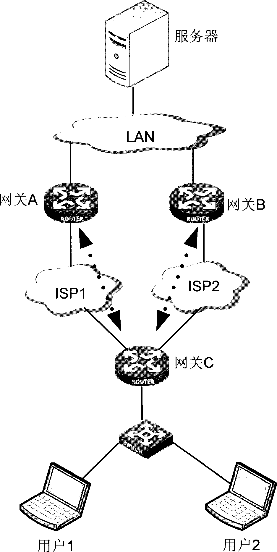
[0039] The main idea of ​​the present invention is to realize the backup of multiple IPSec tunnels based on a single link for the same interface and the same flow, so as to overcome the difference in the prior art that a certain destination node has to be accessed through two or more links respectively. Access devices (such as gateways, routing devices, etc.) to implement IPSec tunnel backup have problems of high cost and switching interruption. The technical solution for realizing IPSec tunnel backup and switching provided by the present invention will be introduced in detail below.

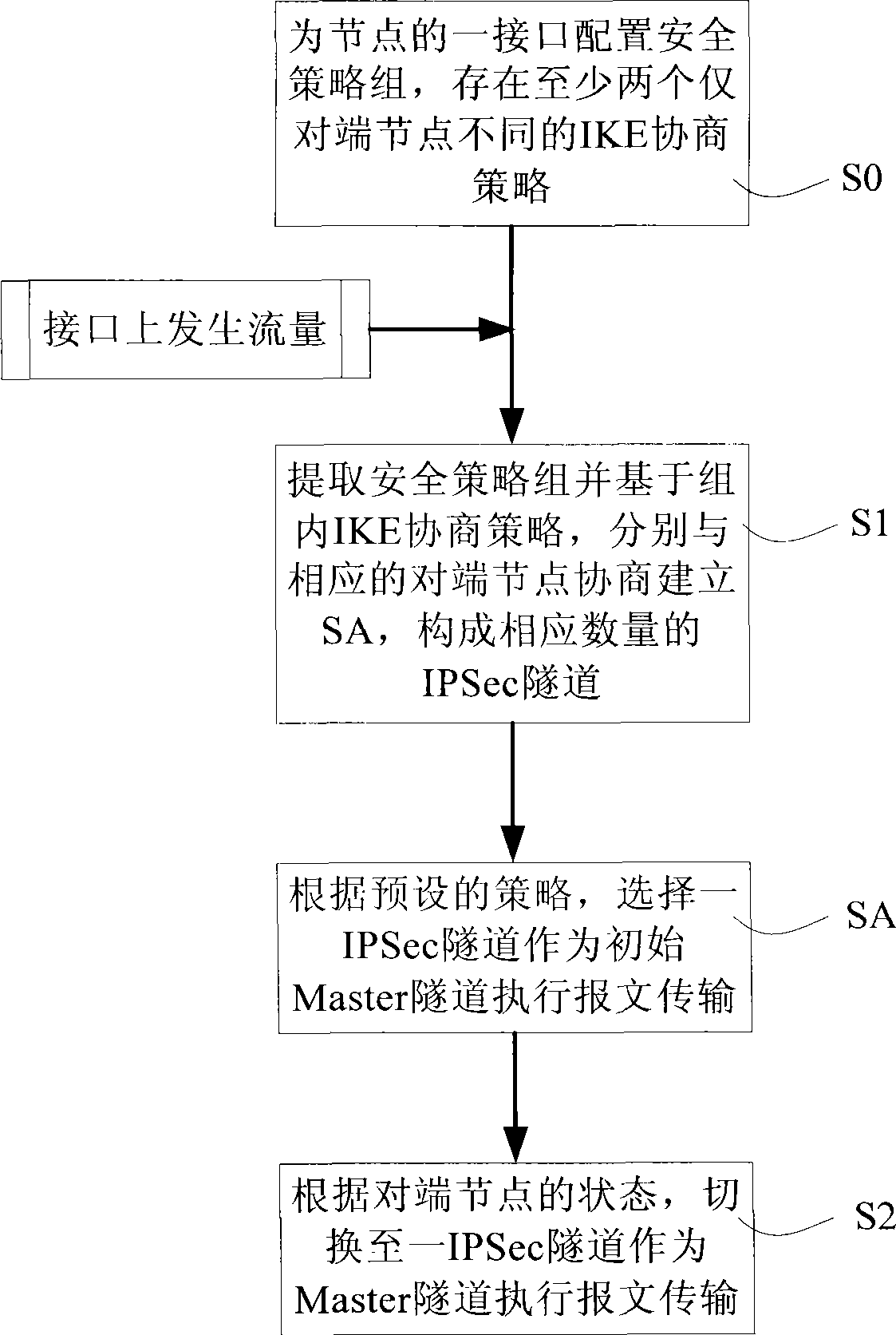
[0040] First, please refer to figure 2 , showing the flow chart of an embodiment of the method for realizing IPSec tunnel backup and switching in the present invention, i...


PUM


Abstract

The invention discloses a method and a system for realizing backup and switching of IPSec tunnel. The method comprises the following steps: configuring a security strategy group for an interface of nodes, wherein the security strategy group at least has two IKE negotiation policies only with different opposite end nodes; and when flow rate generates on the interface, performing the following steps: extracting the security strategy group; and based on the IKE negotiation policy in the group, respectively negotiating with the corresponding opposite end nodes to establish SA for forming IPSec tunnels with corresponding quantity; according to the states of the opposite end nodes, switching to an IPSec tunnel to be used as a Master tunnel to perform message transmission. The invention also discloses node equipment and a network framework. The invention can support IPSec of core node provided with a plurality of breakout gateways to protect communication, thereby effectively reducing cost, shortening time of service interruption, and improving usability of system.

Description

technical field [0001] The invention relates to safe transmission technology, in particular to a method for realizing IPSec tunnel backup and a system for realizing IPSec tunnel backup, and also relates to a node device and a networking framework. Background technique [0002] On the one hand, in order to improve the reliability of the network, core nodes (such as servers) are often connected to the operation network through two or more egress gateways for load sharing or to avoid service flow interruption when an egress gateway fails; in this case In this case, multiple egress gateways are mutually in active backup or load sharing. [0003] On the other hand, in order to ensure the reliability of network communication, nodes often provide IPSec protection in communication. The so-called IPSec (IP Security) is a general mechanism developed by the Internet Engineering Task Force (IETF) to protect communication traffic between nodes at the IP layer. It is mainly protected by ...

Claims


Application Information

Patent Timeline
Patent Type & Authority Applications(China)
IPC IPC(8): H04L12/46H04L12/56H04L1/22H04L29/06H04L45/247
Inventor 李蔚
Owner NEW H3C TECH CO LTD
Why Eureka
Try Eureka