Method for manufacturing molten-metal plated steel band

A hot-dip metal and steel strip technology, applied in hot-dip plating process, metal material coating process, coating, etc., can solve the problems of reduced coating removal, unstable product quality, and reduced surface quality of steel strips, etc., to achieve Suppresses the occurrence of defects on the surface of the coating, suppresses the generation of spatter, and improves the removal power of the coating

Active Publication Date: 2009-05-27
JFE STEEL CORP
View PDF4 Cites 8 Cited by
  • Summary
  • Abstract
  • Description
  • Claims
  • Application Information

AI Technical Summary

Problems solved by technology

[0003] In this gas wiping method, there is a problem that, due to the disorder of the gas jet hitting the steel strip, the molten metal falling below the steel strip scatters to the surroundings, producing so-called spatter, which adheres to the surface of the steel strip, causing damage to the surface of the steel strip. reduction in quality
[0015] With regard to the method of Patent Document 1, in order to improve the wiping force of the edge of the steel strip, the auxiliary nozzle is used to inject gas at a higher gas pressure than the wiping nozzle, so even if the impact positions of the gas jets are made to be the same, the mixing of the gas It can also become violent and produce a lot of spatter, so that the quality of the product is unstable
[0016] Furthermore, in the method of Patent Document 2, since the three nozzles are integrated, the vertical cross-sectional profile angle of the tip of the nozzle becomes large, and it can be seen that as the profile angle becomes obtuse, the plating removability decreases and the scattering of spatter is facilitated.
Furthermore, when a plurality of nozzles are integrated, the total thickness of the nozzle injection openings (width in the longitudinal direction of the steel strip) also increases, which adversely affects the performance of the nozzles.
In addition, in Patent Document 2, there is a description that "the angle of the outer surface of the nozzle is an acute angle", but the angle of the longitudinal section of the tip of the nozzle in the explanatory drawing is about 120°, and the content of the description is completely unclear, and it is not disclosed. according to

Method used


Image

  • Method for manufacturing molten-metal plated steel band
  • Method for manufacturing molten-metal plated steel band
  • Method for manufacturing molten-metal plated steel band

Examples


Embodiment

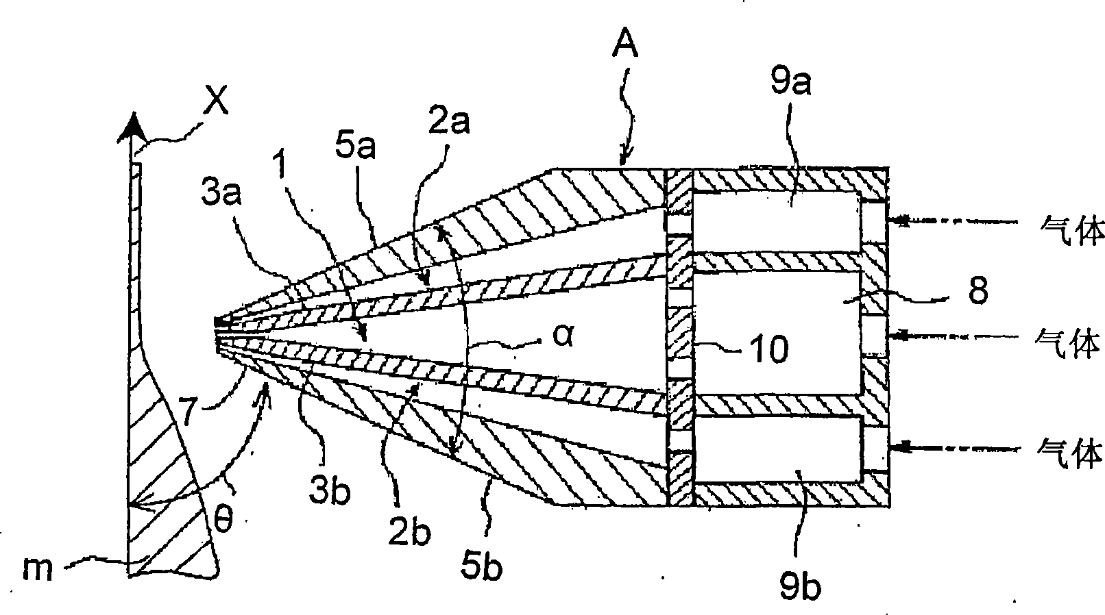
[0095] On the production line of hot-dip galvanized steel strip, various gas wiping nozzles are installed at the position of the gas wiping nozzle above the hot-dip galvanizing bath, and the manufacturing test of the hot-dip galvanized steel strip with a plate thickness of 1.0mm×a plate width of 1200mm is carried out. Manufacturing conditions (same for all tests): Height of gas wiping nozzle from hot-dip galvanizing bath surface: 400mm, hot-dip galvanizing bath temperature: 460°C, main gas injection pressure of gas wiping nozzle: 0.65kgf / cm 2 , The distance between the gas wiping nozzle and the steel strip: 8 mm, the passing speed of the steel strip: 120 mpm, and the amount of coating deposition and the frequency of nozzle clogging in each test were studied (times / hour). The result is as Figure 11 to Figure 15 shown. And, as a gas wiping nozzle, use such as Figure 8 and Figure 10 The upper and lower sides of the main nozzle part are shown in the form of secondary nozzles...


PUM


Abstract

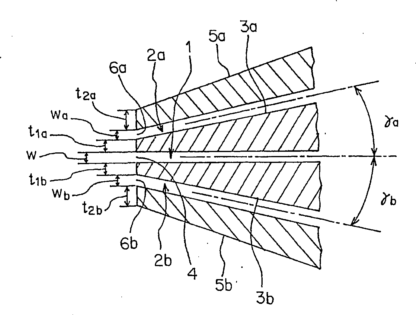
The occurrence of a splash at the time of performing a plating coverage control by using a gas wiping nozzle is suppressed to manufacture a molten-metal plated steel band of a high quality stably. The gas wiping nozzle used is provided with an auxiliary nozzle on the upper and / or lower sides of a main nozzle unit. The auxiliary nozzle unit has its gas injecting direction inclined with respect to the gas injecting direction of the main nozzle unit, and injects a gas jet at a lower speed than that of the gas jet injected from the main nozzle unit. The angle, which is made between the lower face of at least the leading end side portion of the gas wiping nozzle and the steel band is set to 60 degrees or more. Moreover, the gas injection port of the auxiliary nozzle unit is spaced by 5 mm or more in the anti-steel-band direction with respect to the gas injection port of the main nozzle unit, and the gas is so injected from the auxiliary nozzle unit that the auxiliary gas jet from the auxiliary nozzle unit may take a flow velocity at 10 m / s or more at a merging portion with the main gas jet from the main nozzle unit.

Description

technical field [0001] The present invention relates to a method for producing a hot-dip metallized steel strip in which a gas is sprayed from a gas wiping nozzle onto the surface of a steel strip continuously lifted from a hot-dip metal bath to control the amount of coating deposited on the steel strip surface. Background technique [0002] In the continuous hot-dip process, such as Figure 6 As shown, the steel strip X is generally immersed in the coating bath 20 full of molten metal, and then the steel strip X is lifted from the coating bath 20 in the vertical direction, and then the steel strip is sprayed from the gas wiping nozzle 21 opposite to the steel strip. Gas wiping of surfaces with jets of gas. exist Figure 6 Among them, 22 represents a guide roller, and 23 and 24 represent backup rollers. By this gas wiping, excess molten metal is removed to control the coating deposition amount, and at the same time, the molten metal deposited on the surface of the steel str...

Claims


Application Information

Patent Timeline
Patent Type & Authority Applications(China)
IPC IPC(8): C23C2/16C23C2/40
Inventor 武田玄太郎高桥秀行
Owner JFE STEEL CORP
Why Eureka
Try Eureka