Timing chain drive unit

A driving device and timing chain technology, which is applied in the direction of valve driving device, transmission device, valve device, etc., can solve the problems of large peak value, heavy weight of timing chain driving device, and inability to meet small and light weight problems, etc.

Inactive Publication Date: 2009-06-03
TSUBAKIMOTO CHAIN CO
View PDF1 Cites 13 Cited by
  • Summary
  • Abstract
  • Description
  • Claims
  • Application Information

AI Technical Summary

Problems solved by technology

Therefore, in the above-mentioned conventional timing chain drive device 500 in which the chain guide 510 on the tension side that guides and regulates the movement track is arranged on the tension side of the chain CH that circulates, there is this tension fluctuation. There is a danger that the peak value will become too large, so it is necessary to use a chain with a high tensile strength that can allow the maximum tension, and the weight of the timing chain drive device will become heavier, and noise due to high tension will also be generated, which cannot meet the user's requirements. Expected demand for small size, light weight and low noise

Method used


Image

  • Timing chain drive unit
  • Timing chain drive unit
  • Timing chain drive unit

Examples


Embodiment Construction

[0045] Hereinafter, a timing chain driving device according to an embodiment of the present invention will be described with reference to the drawings.

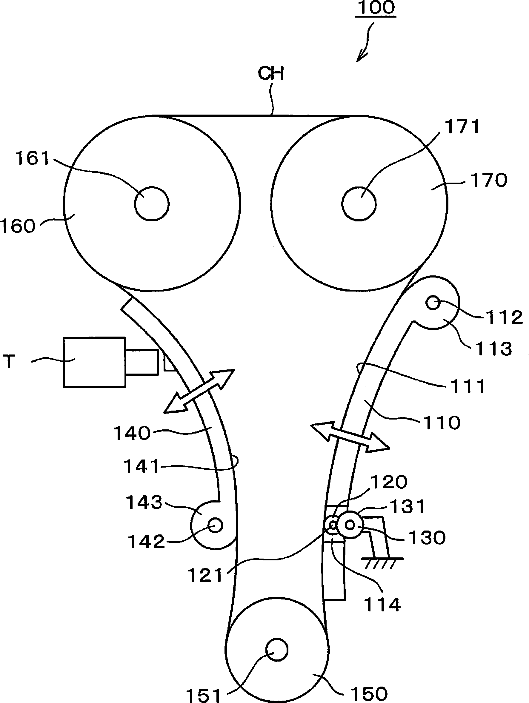
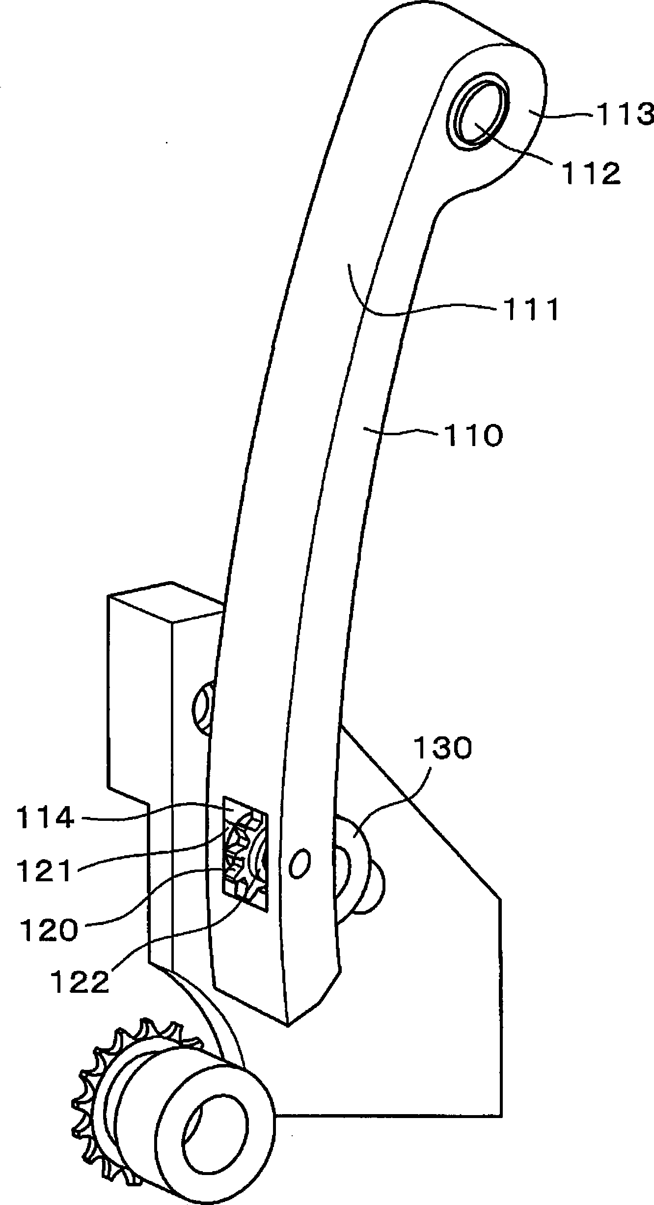
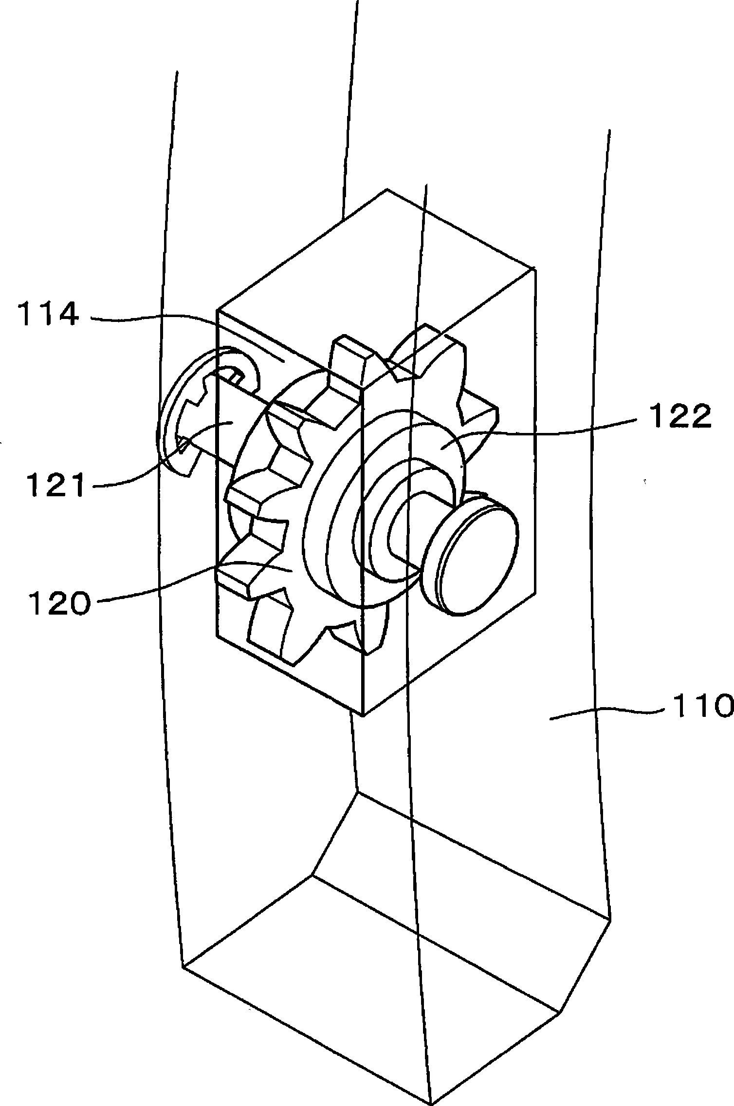
[0046] figure 1 is a schematic diagram of a timing chain drive device according to an embodiment of the present invention, figure 2 yes figure 1 An overall perspective view of the chain guide on the tension side of the first embodiment of the present invention is shown, image 3 yes figure 2 An enlarged partial perspective view of the chain guide on the tensioning side shown, Figure 4 yes figure 2 Side partial sectional view of the chain guide on the tensioning side shown, Figure 5 It is an explanatory diagram of the oscillation of the synchronous sprocket according to an embodiment of the present invention, Figure 6 It is a side view of another embodiment of the synchronous sprocket of the present invention, Figure 7 It is an explanatory diagram of the tooth shape of the negative dedendum of the synchronous s...


PUM


Abstract

The invention provides a timing chain drive unit capable of reducing influence of tension changing, and realizing minature lightweighting of chain and increasing system quietness. In an engine timing chain drive(100), chain guiding pieces (110,14) are provided on the looseness side and the tension side of the chain (CH), and the chain guiding piece (110) on the tension side comprises a synchronizing sprocket (120) in fastening-rotation with the chain (CH) and the chain guiding piece (110) is set in synchronized rotation along with tension variation.

Description

technical field [0001] The present invention relates to a timing chain driving device, which rotates and drives a camshaft that drives intake and exhaust valves of an engine. More specifically, it relates to a guide mechanism for adjusting the tension of the timing chain. Background technique [0002] Until now, the general DOHC type, that is, the timing chain drive 500 in the engine with two camshafts driving the intake and exhaust valves in the cylinder head, such as Figure 13 As shown, the drive sprocket 550, the driven sprocket 560, and the chain CH on the driven sprocket 570 are configured to transmit power through the hanger, and the driven sprocket 560 and the drive sprocket on the slack side of the chain CH Between 550, there is a chain guide 540 on the slack side, which cooperates with the tensioner T and is in sliding contact with the cyclically moving chain CH to apply appropriate tension, and has a chain guide for preventing vibration of the moving chain CH. , S...

Claims


Application Information

Patent Timeline
Patent Type & Authority Applications(China)
IPC IPC(8): F01L1/34F16H7/06
CPCF16H2007/0874F01L1/022F16H7/08F16H2007/0897F16H2007/0802F01L1/02F16H2007/0893
Inventor 中野义和国松幸平桥本裕至
Owner TSUBAKIMOTO CHAIN CO
Why Eureka
Try Eureka