Metallic film type reducing valve

A metal film and pressure reducing valve technology, applied in the field of pressure reducing valves, can solve problems such as oxygen leakage, slow pressure reducing valve speed, and diaphragm damage

Active Publication Date: 2009-06-03
CHANGZHENG ENG
View PDF0 Cites 7 Cited by
  • Summary
  • Abstract
  • Description
  • Claims
  • Application Information

AI Technical Summary

Problems solved by technology

[0005] 1. When the pressure in the pipeline is too high due to leakage in the pressure reducer, the diaphragm may be damaged, which may lead to oxygen leakage
[00

Method used


Image

  • Metallic film type reducing valve
  • Metallic film type reducing valve

Examples


Embodiment Construction

[0016] Next, preferred embodiments of the present invention will be described in detail with reference to the accompanying drawings.

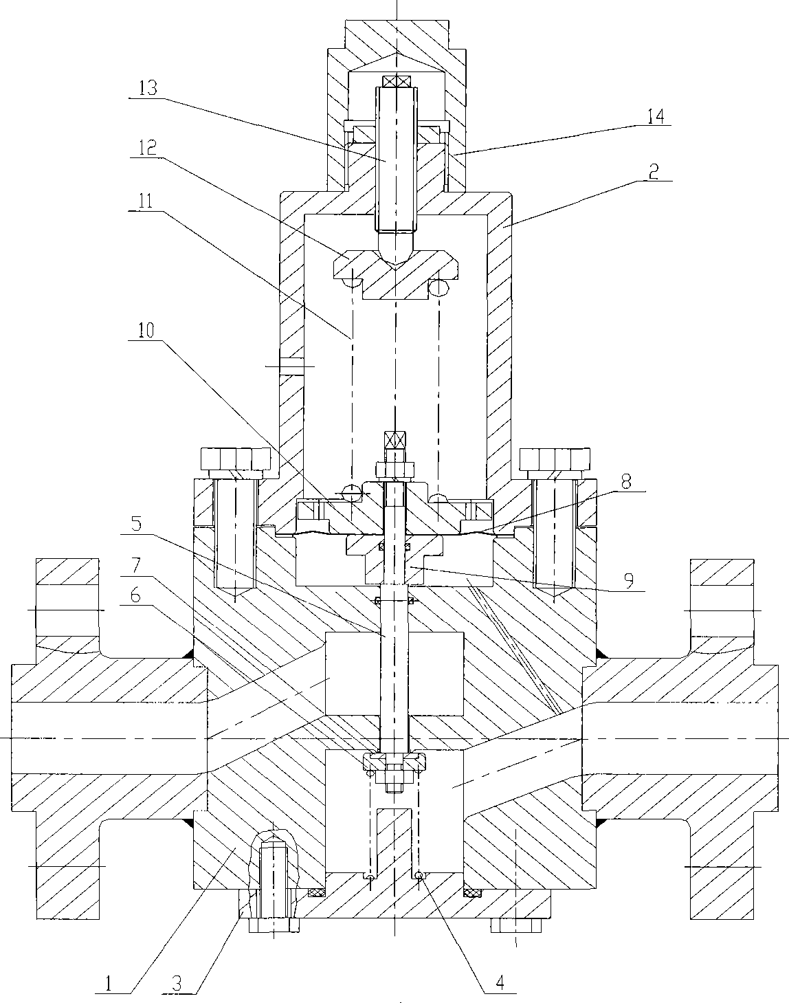
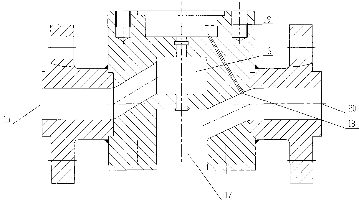
[0017] Such as figure 1 with figure 2 As shown, the pressure reducing valve of the present invention includes: a valve body 1 having a flow passage; a main spring box 2 arranged on the valve body 1; a valve stem 5 having a first end arranged in the flow passage of the valve body 1 and the second end disposed in said mainspring case 2; the diaphragm 8 installed on the second end of the valve stem 5. Wherein, the diaphragm is a corrugated diaphragm made of metal. The diaphragm itself, made of thin metal sheet, has greater strength than materials such as rubber and is not easily damaged. At the same time, the diaphragm is made into a corrugated shape. When the pressure suddenly rises, the shape of the corrugated diaphragm itself can be used to provide pressure buffering, which further eliminates the possibility of diaphragm damage, thereby adv...


PUM


Abstract

The invention provides a metallic film type gas reducing valve, which comprises a valve body (1) provided with a flow passage, a main spring box (2) arranged on the valve body (1), a valve stem (5) and a membrane (8), wherein, the valve stem (5) is provided with a first end part arranged in the flow passage of the valve body (1) and a second end part positioned in the main spring box (2); and the membrane (8) is installed on the second end part of the valve stem (5). By adopting the membrane with a special structure, the membrane can be prevented from being damaged caused by excessive pressure in a pipeline system when the valve stem moves up and down and the vale is sealed.

Description

technical field [0001] The invention relates to a pressure reducing valve, in particular to a metal thin film type pressure reducing valve used in a high-pressure oxygen pipeline. Background technique [0002] The pressure reducing valve is a pressure regulating device that relies on the energy of the pipeline medium to work. There are many classifications of pressure reducing valves, which can be roughly divided into two types: direct acting (self-operated) and indirect acting (commanding) according to their action principles. Compared with the indirect acting pressure reducing valve, the direct acting pressure reducing valve has the advantages of simple structure, reliable operation and low cost. Therefore, in the occasions where the precision of the voltage stabilization is not high, most of the direct acting pressure reducing valves are used. According to the direction of gas flow through the pressure reducing valve, the direct acting pressure reducing valve is divided...

Claims


Application Information

Patent Timeline
IPC IPC(8): F16K17/22F16K27/00
Inventor 李峰俞晓龙刘际
Owner CHANGZHENG ENG
Why Eureka
Try Eureka