Spheroidizing annealing furnace

A spheroidizing annealing furnace and annealing furnace technology, applied in the field of heat treatment, can solve problems such as high cost, increase workpiece production cost, uneven heating of tools, etc., and achieve the effects of reducing contact area, facilitating heating wires, and increasing heat radiation.

Inactive Publication Date: 2019-03-15
嘉善奥力科机械制造有限公司
View PDF6 Cites 2 Cited by
  • Summary
  • Abstract
  • Description
  • Claims
  • Application Information

AI Technical Summary

Problems solved by technology

However, when the spheroidizing annealing furnace heats the workpiece, the hot air in the inner barrel can only flow up and down in the inner barrel, or it is not enough to form hot air, which will easily lead to uneven heating of the tools in the inner barrel, and at the same time, the maintenance cost of the existing spheroidizing annealing furnace Expensive, increases workpiece production costs

Method used


Image

  • Spheroidizing annealing furnace
  • Spheroidizing annealing furnace
  • Spheroidizing annealing furnace

Examples


Embodiment 1

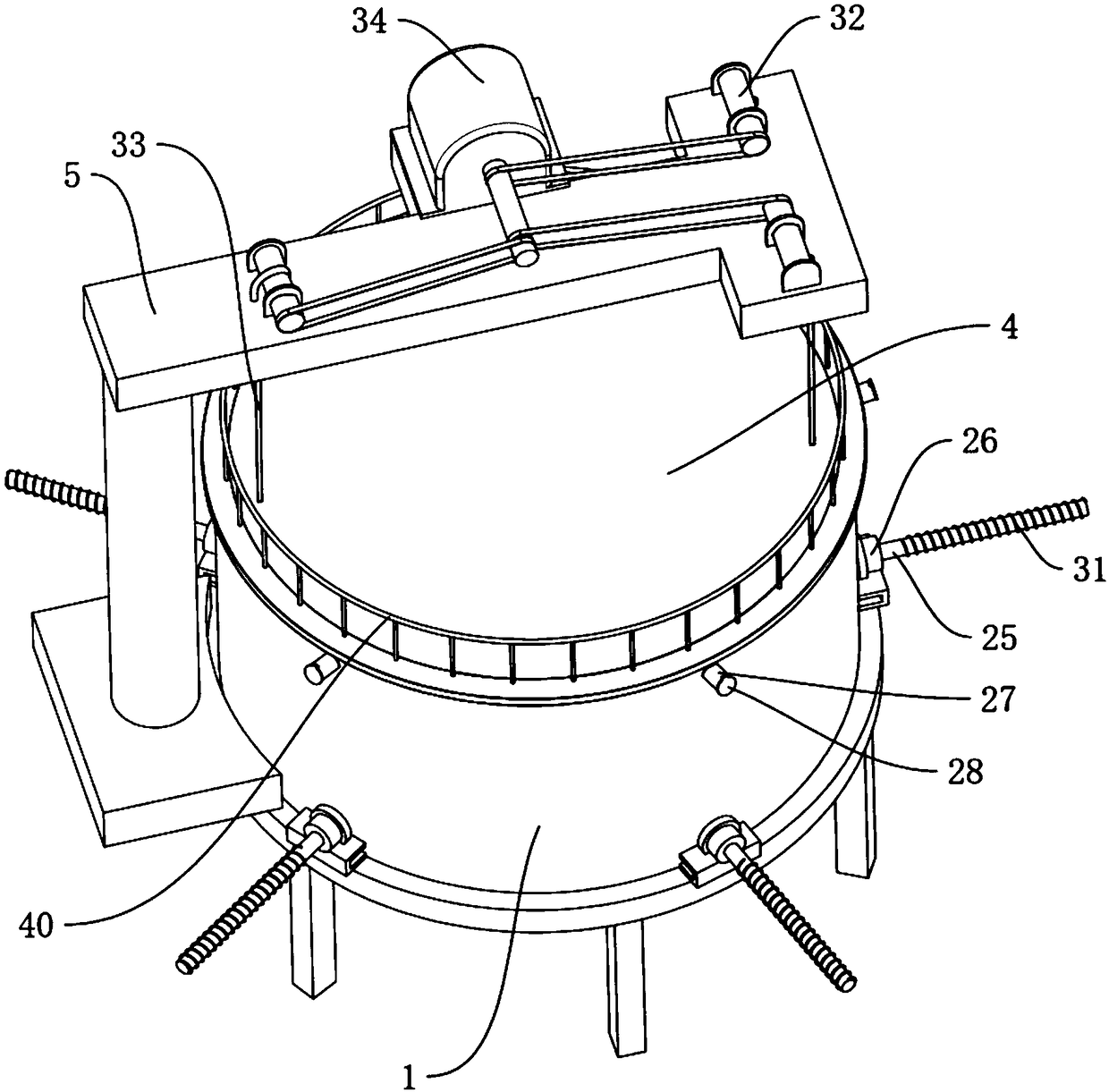
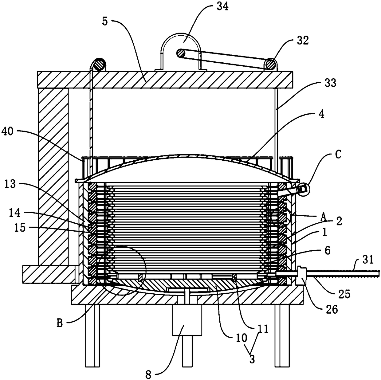
[0034] Embodiment one: if Figure 1 to Figure 7 As shown, a kind of spheroidizing annealing furnace proposed by the present invention includes an annealing furnace main body 1, an inner barrel 2, a loading platform 3, a furnace cover 4 and a cantilever 5, and a convection system is arranged in the annealing furnace main body 1 for controlling the annealing furnace The thermal insulation system for the main body 1 and the heating system for heating the material in the inner barrel 2.

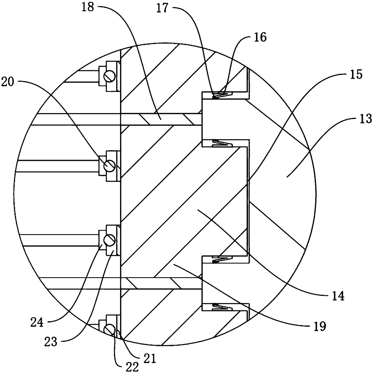
[0035] The convection system includes a convection barrel 6 installed in the inner cavity of the inner barrel 2. The bottom surface of the convection barrel 6 is open. The hot air in 6 flows into the gap 7 between the convection barrel 6 and the inner barrel 2. The side walls of the convection barrel 6 and the inner barrel 2 are corrugated. The convection fan 8. In this way, the hot air in the convection barrel 6 is driven to flow downward by the convection fan 8, and the hot air at the bottom ...

Embodiment 2

[0052] Embodiment 2 is different from Embodiment 1 in that: as Figure 8 and Figure 9 As shown, an anti-sway device is provided between the cantilever 5 and the furnace cover 4. The anti-sway device includes a first sleeve 35 sleeved on the corresponding chain 33 and fixed to the lower end surface of the cantilever 5, sleeved on the corresponding chain 33 and fixedly connected. The second bushing 36 on the upper end surface of the furnace cover 4, the third bushing 37 is pierced between the first bushing 35 and the second bushing 36, the third bushing 37 is sleeved on the corresponding chain 33, and the third bushing The upper and lower ends of the tube 37 are respectively passed through the first sleeve 35 and the second sleeve 36, and there is a gap between the first sleeve 35 and the third sleeve 37 to prevent the third sleeve 37 and the first sleeve 35 from Separate anti-breakout components. In this way, the first casing 35 , the second casing 36 and the third casing 37...


PUM


Abstract

The invention discloses a spheroidizing annealing furnace, and the technical scheme is that the furnace a furnace body, an inner barrel, a loading platform, a furnace cover and a cantilever. The furnace body is provided with a convection system, a heat preservation system and a heating system. The convection system comprises a convection fan arranged at the bottom of the furnace body and a convection barrel arranged in the inner cavity of the inner barrel. The heat preservation system comprises a plurality of heat preservation cotton blocks arranged on the inner wall of the furnace body, a mounting frame fixed on the inner wall of the furnace body and used for mounting a plurality of heat preservation cotton blocks, and a connecting assembly arranged between the heat preservation cotton blocks and the mounting frame to keep the heat preservation cotton blocks fixed on the mounting frame. The invention can effectively improve the hot air convection efficiency in the inner barrel, and ensure that the materials can be uniformly heated, and at the same time, through a plurality of independent thermal insulation cotton blocks, one of the thermal insulation cotton blocks can be replacedindependently, thereby reducing the maintenance cost.

Description

technical field [0001] The invention relates to the field of heat treatment, in particular to a spheroidizing annealing furnace. Background technique [0002] The spheroidizing annealing furnace is mainly suitable for heat treatment of eutectoid steel and hypereutectoid steel workpieces such as carbon tool steel, alloy tool steel, bearing steel, etc. After spheroidizing annealing in the spheroidizing annealing furnace, the spherical pearlite structure is obtained, and the cementite in it is spherical particles, dispersedly distributed on the ferrite matrix. Compared with the flaky pearlite, it not only has lower hardness, but also facilitates cutting. Moreover, during quenching and heating, the austenite grains are not easy to grow, and the deformation and cracking tendency of the workpiece are small during cooling. [0003] The existing spheroidizing annealing furnace heats the inner barrel by means of a heating wire to heat treat the tool. However, when the spheroidizing...

Claims


Application Information

Patent Timeline
Patent Type & Authority Applications(China)
IPC IPC(8): C21D1/32C21D1/34C21D9/00
CPCC21D1/32C21D1/34C21D9/00
Inventor 钱忠钱建春柏才兰池秀钢
Owner 嘉善奥力科机械制造有限公司
Why Eureka
Try Eureka