Embedding device for underground heat exchanger of earth source heat pump

A technology of underground heat exchangers and ground source heat pumps, which is applied to lighting and heating equipment, heating methods, and household heating. operation, ensure construction quality, and improve the effect of embedding speed

Inactive Publication Date: 2010-06-16
CHONGQING UNIV
View PDF4 Cites 0 Cited by
  • Summary
  • Abstract
  • Description
  • Claims
  • Application Information

AI Technical Summary

Problems solved by technology

According to the current actual engineering, the main disadvantages of manual lowering are: slow speed, need a lot of manpower, heavy workload, and long construction period
The main disadvantage of this device is: in the process of using the drilling machine to transport the lower pipe, the drilling machine cannot perform the drilling operation, so the drilling speed is reduced and the construction period is prolonged; If it is stuck on the wall of the hole, if the tube is forced down, it will easily cause damage to the heat exchanger, and there is a potential danger to the person who is down the tube near the drilling machine; the drill pipe of the drilling machine is in the middle of the U-shaped tube, resulting in a fixed ground It is impossible to install pipe clips that bury pipes and keep them at a certain distance; the diameter of the drill pipe is relatively large. Increased radius, thereby increasing construction costs

Method used


Image

  • Embedding device for underground heat exchanger of earth source heat pump
  • Embedding device for underground heat exchanger of earth source heat pump
  • Embedding device for underground heat exchanger of earth source heat pump

Examples


Embodiment 1

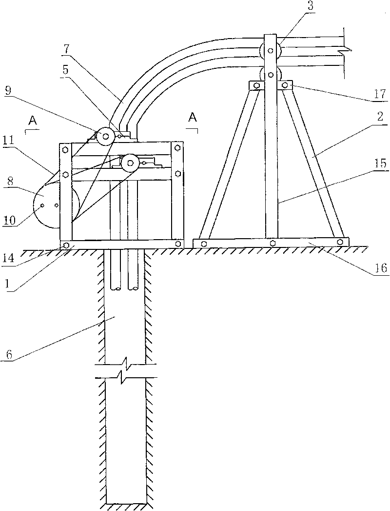
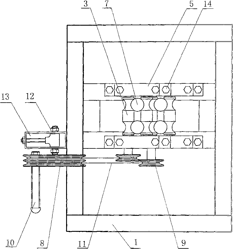
[0021] like figure 1 , 2 , 3, a ground source heat pump underground heat exchanger embedding device, mainly by the bracket 1, arc groove roller shaft 3, handle 10, driving wheel 8, driven wheel 9, support frame and so on. The bracket 1 is made of angle steel, and is assembled into a detachable bracket by bolts and nuts 14, and its height is 800 mm. In the middle of the upper end of the bracket 1, it is divided into upper and lower layers, and two angle steels are fixed by bolts and nuts 14 respectively. The length of the shaft 3 is determined, and holes are respectively arranged in the middle of the opposite inner surfaces of the four angle steels. There are two pairs (i.e. 4) of arc groove roller shafts 3, each of which is formed by round steel at both ends of the roller shaft 3 with concave arc grooves, and is provided with thread. The size and spacing of the arc grooves at both ends are determined according to the outer diameter of the straight pipe of the buried U-shap...

Embodiment 2

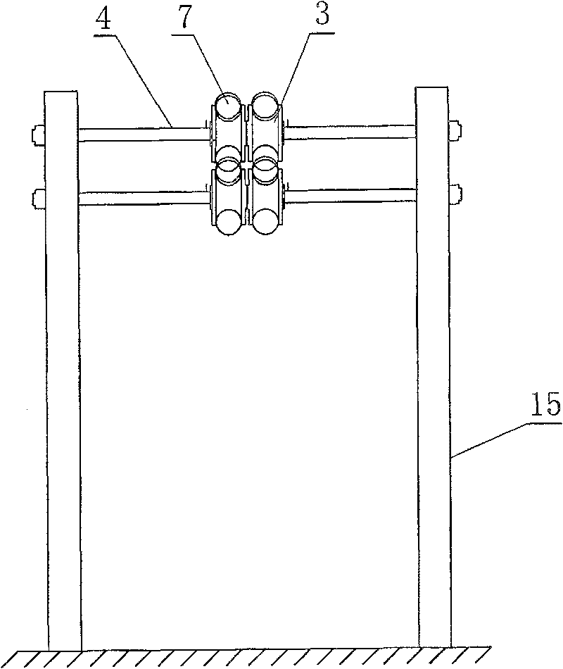
[0023] A device for embedding an underground heat exchanger of a ground source heat pump, the same as that in Embodiment 1, characterized in that the height of the bracket 1 is 900 mm. The distance between the upper and lower layers of angle steel of the bracket 1 is 90mm. The driven wheel 9 is a single sheave with a diameter of 50mm, and the driving wheel 8 is a double sheave with a diameter of 160mm. The height of the two straight columns 15 is 1450 mm, the distance between them is 450 mm, and the distance between the two circular through holes at the top of the two straight columns 15 is 90 mm. The length of the angle steel cross-arm 17 welded respectively on the top of the straight post 15 (i.e. below the through hole) is 10mm.

Embodiment 3

[0025] An embedding device for an underground heat exchanger of a ground source heat pump, the same as in Embodiment 1, characterized in that the height of the bracket 1 is 700 mm. The distance between the upper and lower layers of angle steel of the bracket 1 is 70 mm. The driven wheel 9 is a single sheave with a diameter of 70mm, and the driving wheel 8 is a double sheave with a diameter of 140mm. The height of the two straight columns 15 is 1400 mm, the distance between them is 400 mm, and the distance between the two circular through holes at the top of the two straight columns 15 is 70 mm. The length of the angle steel cross-arm 17 welded respectively on the top of the straight post 15 (i.e. below the through hole) is 7mm.


PUM


Abstract

The invention discloses an embedding device for the underground heat exchanger of an earth source heat pump, which relates to an assist device for vertically embedding the underground heat exchanger of the earth source heat pump. The device of the invention mainly comprises a support, an arc groove roll shaft, a handle, a driving wheel, a driven wheel and a support frame. The device of the invention not only can increase the embedding speed of the underground heat exchanger of the earth source heat pump, but also can guarantee the construction quality, has the characteristics of simple operation, energy conservation, convenient field operation and low cost, and is easy to be popularized and applied. The device of the invention is wildly used for vertical embedment of the underground heat exchangers of the earth source heat pump in all parts of China.

Description

1. Technical field: [0001] The invention belongs to the technical field of embedding of a ground source heat pump system, in particular to an auxiliary device for vertically embedding an underground heat exchanger of a ground source heat pump. 2. Background technology: [0002] According to incomplete statistics, my country's building energy consumption has reached 27.5% of the total energy consumption at present, and this figure will continue to increase with the rapid development of my country's construction industry. Therefore, with the establishment of the basic national policy of energy conservation and emission reduction, the development of building energy conservation work is even more significant. According to the country's goal of achieving 65% energy saving in buildings, in addition to improving building enclosures to achieve energy savings of 30% to 35%, energy-consuming equipment and systems must also achieve energy savings of more than 30%. The use of renewable...

Claims


Application Information

Patent Timeline
Patent Type & Authority Patents(China)
IPC IPC(8): F24F13/30
Inventor 丁勇李百战周海峰李楠刘猛刘红高亚锋连大旗蔡珍红陈金华
Owner CHONGQING UNIV
Why Eureka
Try Eureka