
Quench-detection circuit of high-temperature superconducting magnet

A high-temperature superconducting and detection circuit technology, which is applied in the direction of measuring electricity, measuring electrical variables, and measuring devices, can solve the problems of permanent damage to high-temperature superconducting magnets, damage to high-temperature superconducting magnets, and slow quench propagation speed, etc., to achieve The effect of fast speed, improved accuracy, and reduced influence of interference signals

Active Publication Date: 2009-06-03
CHINA ELECTRIC POWER RES INST +1
View PDF0 Cites 28 Cited by
  • Summary
  • Abstract
  • Description
  • Claims
  • Application Information

AI Technical Summary

Problems solved by technology

On the one hand, since the quench always starts from one point, and then diffuses outward through ohmic heat and heat conduction, the area that first turns to the normal state stays in the ohmic heating state for the longest time and has the highest temperature rise, and local overheating may burn the insulation or burn At the same time, quenching may also generate high voltage to cause insulation breakdown. Quenching of high-temperature superconducting magnets is accompanied by high-temperature superconducting overcurrent and heat generation. If measures are not taken in time to transfer the energy stored in the high-temperature superconducting coil, these energy will be dissipated in the form of heat through the HTS coils, severe localized temperature rise may damage the HTS magnet
[0004] Superconducting magnets include high-temperature superconducting magnets and low-temperature superconducting magnets. Generally speaking, the quench propagation speed of high-temperature superconducting magnets is two to three orders of magnitude slower than that of low-temperature superconducting magnets. A hot spot is formed locally in the superconducting magnet, and the heat can only be diffused in a small range, resulting in permanent damage to the high-temperature superconducting magnet

Method used


Image

  • Quench-detection circuit of high-temperature superconducting magnet
  • Quench-detection circuit of high-temperature superconducting magnet
  • Quench-detection circuit of high-temperature superconducting magnet

Examples


Embodiment Construction

[0019] The present invention will be further described below in conjunction with the accompanying drawings.

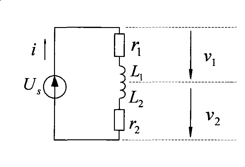
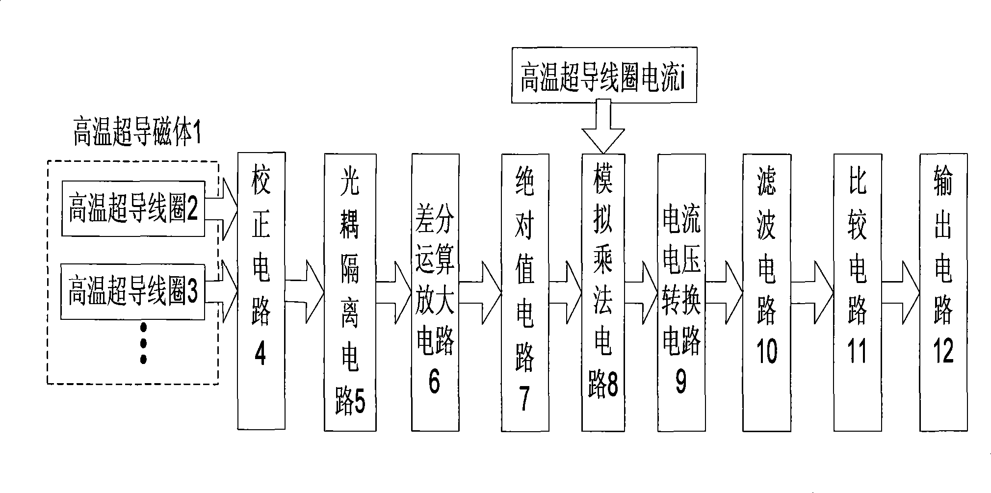
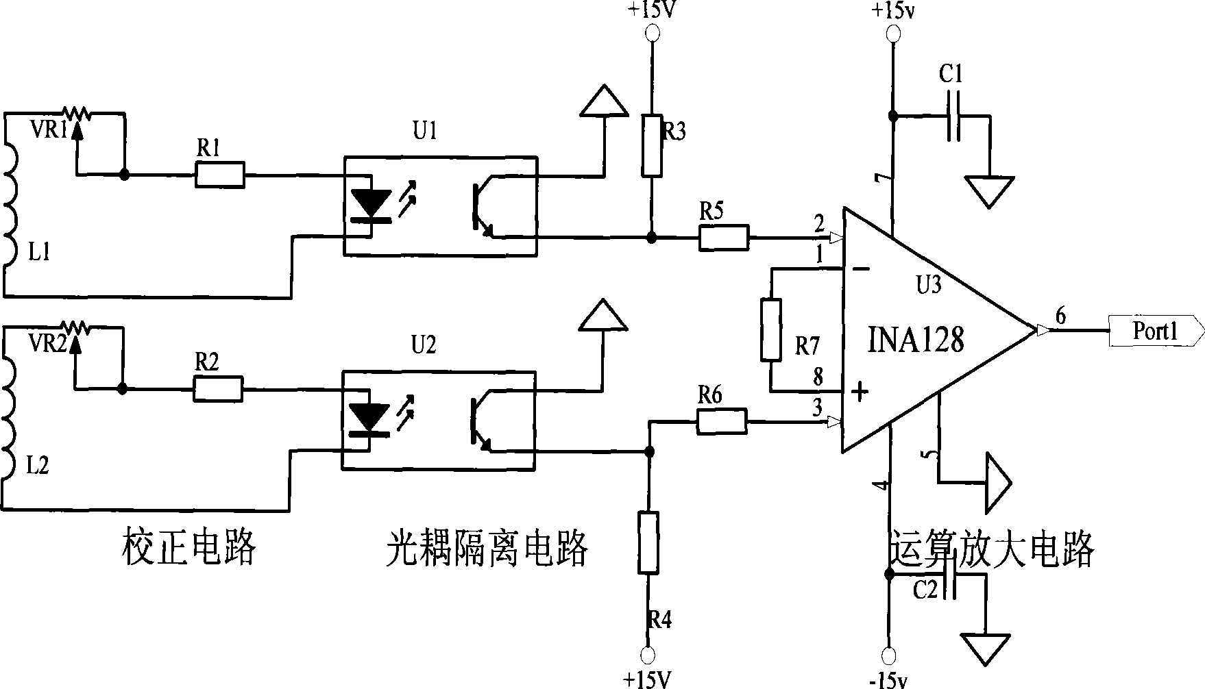
[0020] figure 2 It shows a schematic diagram of quench detection for high-temperature superconducting magnets, which consists of the following parts: high-temperature superconducting magnet 1, high-temperature superconducting coil 2, high-temperature superconducting coil 3, correction circuit 4, optocoupler isolation circuit 5, differential calculation Amplifying circuit 6, absolute value circuit 7, analog multiplication circuit 8, current-voltage conversion circuit 9, filter circuit 10, comparison circuit 11 and output circuit 12, wherein high temperature superconducting magnet 1 is composed of high temperature superconducting coil 2, high temperature superconducting coil 3 high temperature superconducting coils connected in series. Taking the high-temperature superconducting coil 2 and the high-temperature superconducting coil 3 as an example, the specific implemen...


PUM


Abstract

The invention relates to a quench-detection circuit of a high-temperature superconducting magnet, in particular to a circuit for detecting whether quench occurs to the high-temperature superconducting magnet or not. The circuit comprises the high-temperature superconducting magnet, a correction circuit, an optocoupler isolation circuit, a differential operational amplifier circuit, an absolute value circuit, an analog multiplication circuit, a current-voltage conversion circuit, a filter circuit, comparison circuits, an output circuit, and the like, wherein, the high-temperature superconducting magnet is formed by connecting a plurality of high-temperature superconducting coils in series, each two high-temperature superconducting coils are taken as one group for carrying out the comparison, output ends of each group of the comparison circuits are connected in parallel, a quench signal is output, and the quench signal is input to a protection circuit, thereby avoiding the high-temperature superconducting magnet from being damaged.

Description

technical field [0001] The invention relates to a quench detection circuit for high-temperature superconducting magnets. More specifically, the present invention relates to a circuit for detecting whether a quench has occurred in a high temperature superconducting magnet. Background technique [0002] Superconducting power devices in power systems will inevitably encounter various dynamic processes such as system short-circuit faults, and withstand the impact of short-circuit large currents and unbalanced currents. The superconducting magnets in superconducting power devices may suffer from excessive short-circuit Quenched by current action. The quenching of superconducting magnets not only changes the electrical parameters of superconducting power devices, but also has a bad influence on the safe, stable and economical operation of power systems. [0003] For the high-temperature superconducting magnet itself, the high-temperature superconducting magnet can only exhibit s...

Claims


Application Information

Patent Timeline
IPC IPC(8): G01R31/00
Inventor 魏斌丘明张宏杰诸嘉慧
Owner CHINA ELECTRIC POWER RES INST
Learn More