Socket for cathode tube

A technology for cathode tubes and tubes, which is applied in the direction of discharge tubes, coupling devices, lighting and heating equipment, etc., and can solve problems such as unstable electrical connections, tilted clamping angles, and broken cold cathode tubes 1

Inactive Publication Date: 2009-06-03
SMK CO LTD
View PDF0 Cites 0 Cited by
  • Summary
  • Abstract
  • Description
  • Claims
  • Application Information

AI Technical Summary

Problems solved by technology

[0005] Therefore, when there is a difference in expansion and contraction between the cold cathode tube 1 and the metal frame 4 and the circuit board 3 due to the heat generated when the tube emits light, since the socket 110 is fixed on the circuit board, there is a gap between the cold cathode tube terminal part 2 and the clamping position. Dislocation occurs on the clamping contact surface of the part, and there is a problem of unstable electrical connection
[0006] In addition, with the enlargement of LCD TVs in recent years, the length of cold-cathode tubes has been lengthened, and the slight error in the processing of socket 110 or the slight inclination of socket 110 to the installation of circuit board 3 will make the cold-cathode tube terminal part 2 The clamping angle creates a tilt, as in the Figure 7 As shown in (c), tension will be added to the cold cathode tube 1 to make it bend longitudinally, and in the worst case, the cold cathode tube 1 may be broken
[0007] In Japanese Patent Laying-Open No. 45628 (Patent Document 1), although an elastically deformable leaf spring is provided as a laser excitation lamp holder, the publication discloses The technology is used to prevent poor contact when the lamp holder is fastened to the terminal holder with bolts in the state where the lamp holder and the lamp electrode terminal are welded, and it is not suitable for the socket structure of the application using clamping installation. Technology

Method used


Image

  • Socket for cathode tube
  • Socket for cathode tube
  • Socket for cathode tube

Examples


Embodiment Construction

[0040] Embodiments of the socket for cathode tubes according to the present invention will be described below with reference to the drawings.

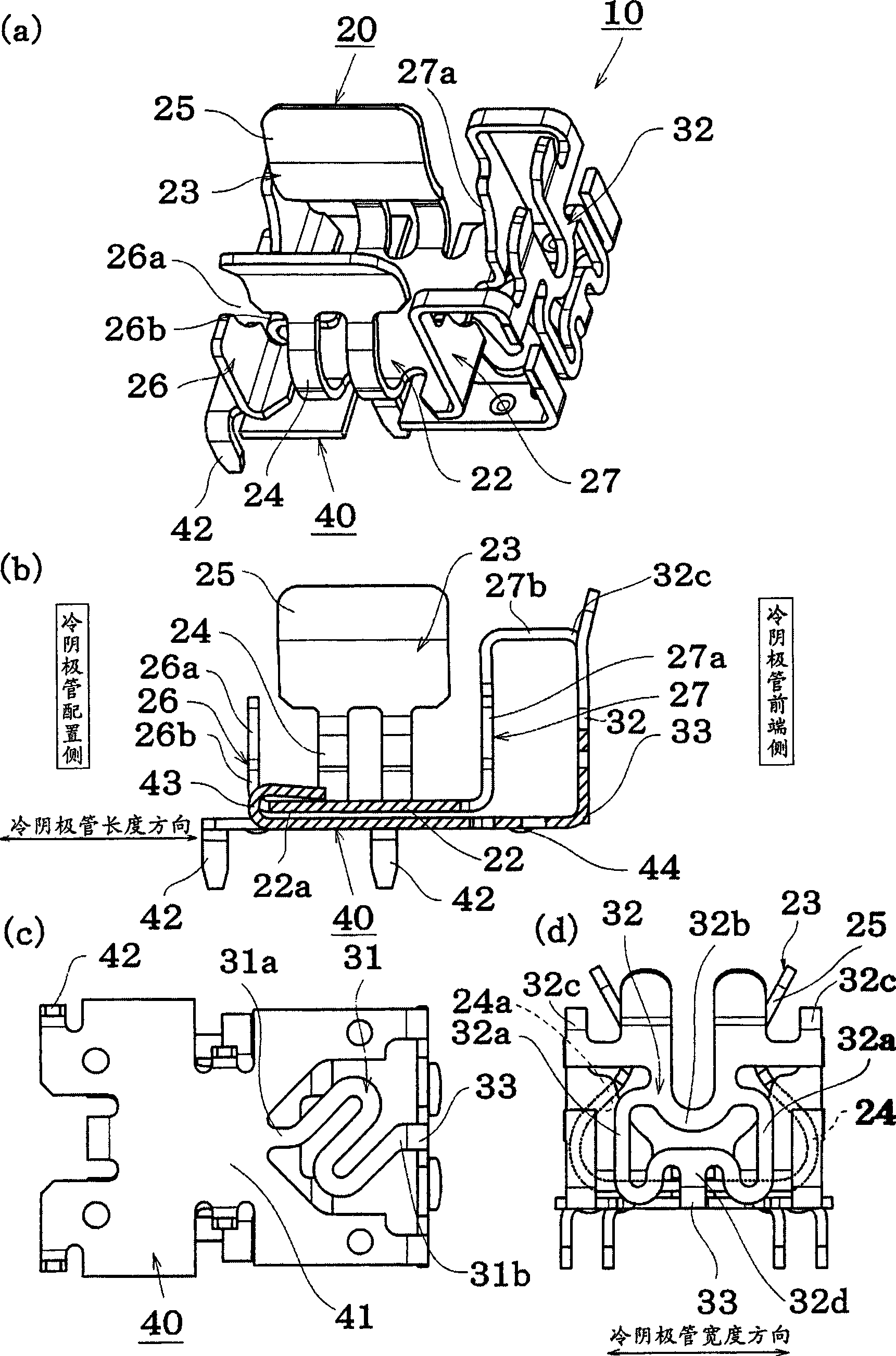
[0041] figure 1 , figure 2 It is an explanatory diagram of the socket, figure 1 (a) represents a perspective view, figure 1 (b) represents a longitudinal sectional view cut along the length direction of the installed cold cathode tube, figure 1 (c) represents a bottom view, figure 1 (d) shows a view seen from the side of the front end of the cold cathode tube.

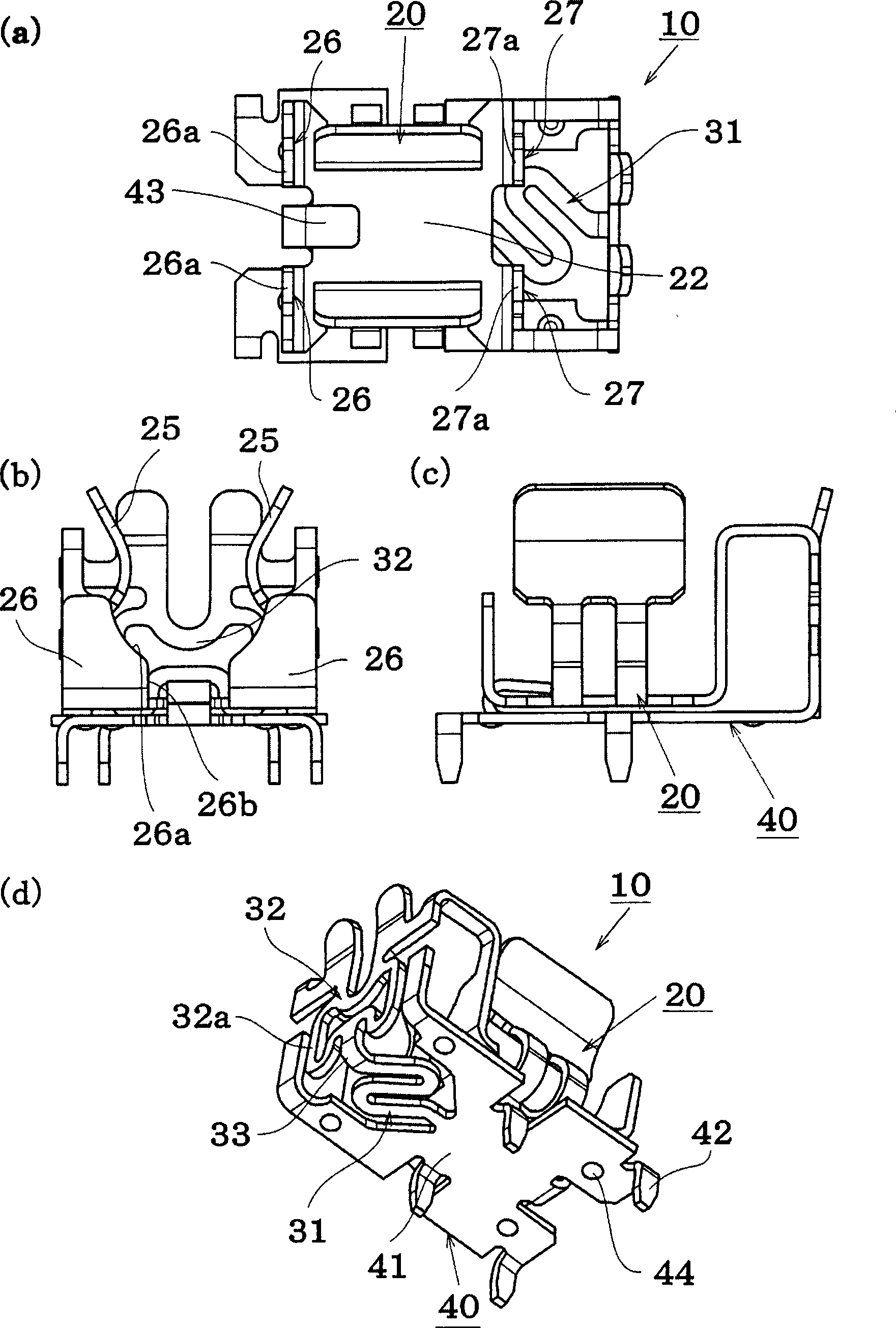
[0042] figure 2 (a) represents a top view, figure 2 (b) shows a view seen from the cold cathode tube arrangement side, figure 2 (c) shows a view seen from the side in the longitudinal direction of the cold-cathode tube, figure 2 (d) shows a perspective view seen from the bottom side.

[0043] The socket 10 has a clamping part 20 for clamping and connecting the terminal part of the cold cathode tube and a circuit board mounting part 40 installed on the circuit...


PUM


Abstract

The present invention relates to a socket for a cathode tube. The aim of the invention is to provide a socket for a cathode tube, capable of easily absorbing a shrinking difference generated between the cathode tube and a circuit board, a frame and the like due to a temperature difference caused by turning on and off the cathode tube, and absorbing processing error and mounting error of the socket. The socket of the invention is characterized in that a clamping part for holding the side part of a cathode tube terminal part is connected with a mounting part electrically connected by a circuit board by two ends of a first elastic distortion part and a seond elastic distortion part arranged in a basal rightanglle direction relative to the first elastic distortion part.

Description

technical field [0001] The invention relates to a socket for a cathode tube, and is particularly suitable for a socket for a cold cathode tube such as a backlight of a liquid crystal display device. Background technique [0002] As a socket structure for mounting a cold cathode tube (Cold Cathode Fluorescent Lamp: CCFL tube) used in the backlight of a liquid crystal display device such as a liquid crystal television on a rigid circuit board, there are known socket structures such as Figure 7 (a) Structure shown. [0003] The socket 110 has clamping portions 120 clamping the terminal portions 2 provided at both ends of the cold cathode tube 1 . [0004] In addition, the socket 110 is mounted on the circuit board 3, and the circuit board 3 is mounted on the metal frame 4 or the like. [0005] Therefore, when there is a difference in expansion and contraction between the cold cathode tube 1 and the metal frame 4 and the circuit board 3 due to the heat generated when the tube ...

Claims


Application Information

Patent Timeline
Patent Type & Authority Applications(China)
IPC IPC(8): H01R33/02H01R13/11
CPCF21V19/00G02F1/133604H01R33/02
Inventor 田中克佳竹田利光
Owner SMK CO LTD
Why Eureka
Try Eureka