
Universal electronic potentiometer module

An electronic potentiometer and general electronic technology, applied in the field of general electronic potentiometer units, can solve problems such as easy damage, limited function expansion, fear of vibration, etc., and achieve the effects of convenient memory, improved research and development efficiency, and simplified design.

Inactive Publication Date: 2011-09-07
武汉市创佳源电子有限公司
View PDF0 Cites 0 Cited by
  • Summary
  • Abstract
  • Description
  • Claims
  • Application Information

AI Technical Summary

Problems solved by technology

[0002] Mechanical potentiometers have been used for nearly a hundred years. Mechanical potentiometers have mechanical wear, are afraid of vibration, and are easily damaged by frequent actions. Dial switches and resistor networks can also form potentiometers, but there are mechanical breakpoints. Cannot be used in case of continuous request
[0003] There is a digital potentiometer integrated chip, but it requires a large number of peripheral circuits and secondary design to realize the complete function of the potentiometer. Since the output resistor network is integrated together, the function expansion has great limitations.

Method used


Image

  • Universal electronic potentiometer module
  • Universal electronic potentiometer module
  • Universal electronic potentiometer module

Examples


Embodiment Construction

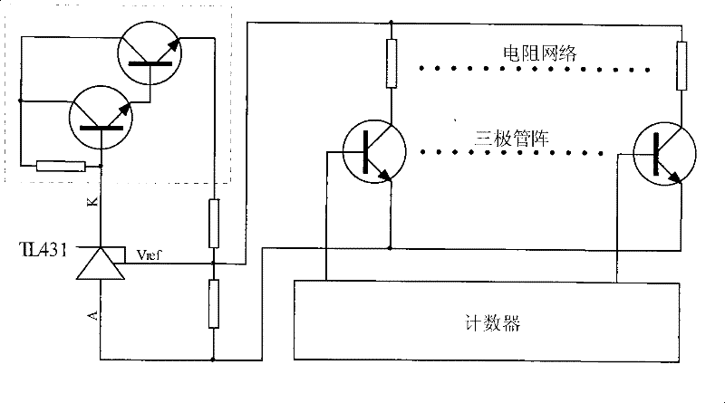
[0028] in Figure II In the voltage output mode scheme shown, the electronic potentiometer adopts the reverse adjustment method shown in Figure 6, because the resistance network is all connected in parallel. When the count value increases, the output resistance decreases. According to the working principle of TL431, it works normally. Within the range (2.5V-36V), when the resistance value between Vref and A decreases, the voltage between K and A increases. When the resistance value between Vref and A increases, the voltage between K and A increases. When the voltage is reduced, when the resistor network is arranged with an appropriate resistance value according to the 8-4-2-1 code, the linear relationship between the output voltage and the count value can be accurately achieved.

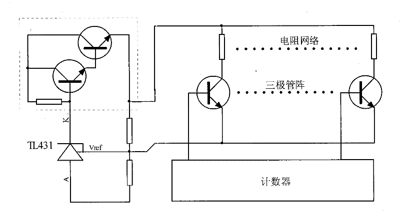
[0029] The same is true Figure three In the voltage output mode scheme shown, the electronic potentiometer adopts Figure Seven In the positive adjustment method shown, when the count value increases, t...


PUM


Abstract

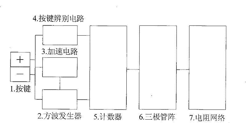
The invention discloses a universal electronic potentiometer module. Functional circuits such as a key switch, a square generator, an accelerating circuit, a keystroke distinguishing circuit, a counter, an NPN-typed triode array with the collector open and a resistance network and the like are electrically connected to form a complete electronic potentiometer apparatus which outputs a passive power to realize the function of a common potentiometer and expand new functions. The invention has a resistance output mode and a voltage output mode, can also lead an output value to be passively adjusted or reversely adjusted; the modes and functions can lead the module to be very easily and directly connected with other various external active circuits, and are broadly applied to various electronic fields. The technical principle construction realizing method of the invention is as follow: 1) using separated elements and small scale integrated circuits; 2) using the singlechip like AT89C2051 as a core; 3) integrating the function components and elements which can be integrated.

Description

Technical field [0001] The invention uses all electronic components to form a complete universal electronic potentiometer unit, which can be used as a multifunctional precision potentiometer in various electronic fields to realize and expand traditional mechanical potentiometers, multi-turn potentiometers, dial switches, etc. Mechanical devices and digital potentiometer integrated chip functions. Background technique [0002] Mechanical potentiometers have been in use for nearly a hundred years. Mechanical potentiometers are subject to mechanical wear, vibration, and frequent actions. They are easily damaged. Dip switches and resistor networks can also form potentiometers, but there are mechanical breakpoints. There are many changes in resistance. Cannot be used under continuous request. [0003] There is a digital potentiometer integrated chip, but it requires a large number of peripheral circuits and secondary design to realize the complete function of the potentiometer. Because...

Claims


Application Information

Patent Timeline
Patent Type & Authority Patents(China)
IPC IPC(8): H03J5/04
Inventor 程杰保
Owner 武汉市创佳源电子有限公司
Learn More