Scroll compressor
A scroll compressor and scroll technology, applied in the field of scroll compressors, can solve problems such as difficulty in tracking temperature gradients
- Summary
- Abstract
- Description
- Claims
- Application Information
AI Technical Summary
Problems solved by technology
Method used
Image
Examples
no. 1 approach
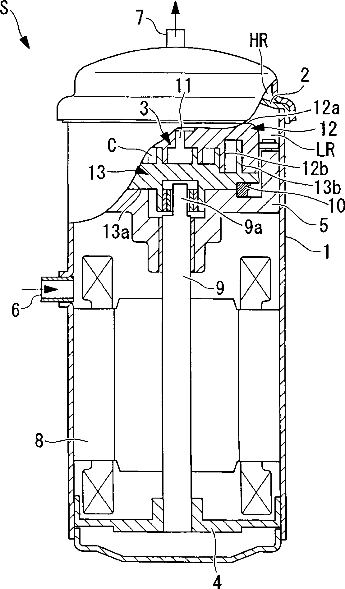
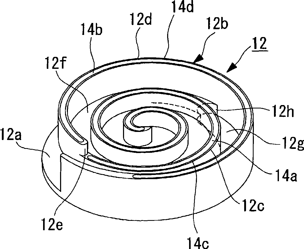
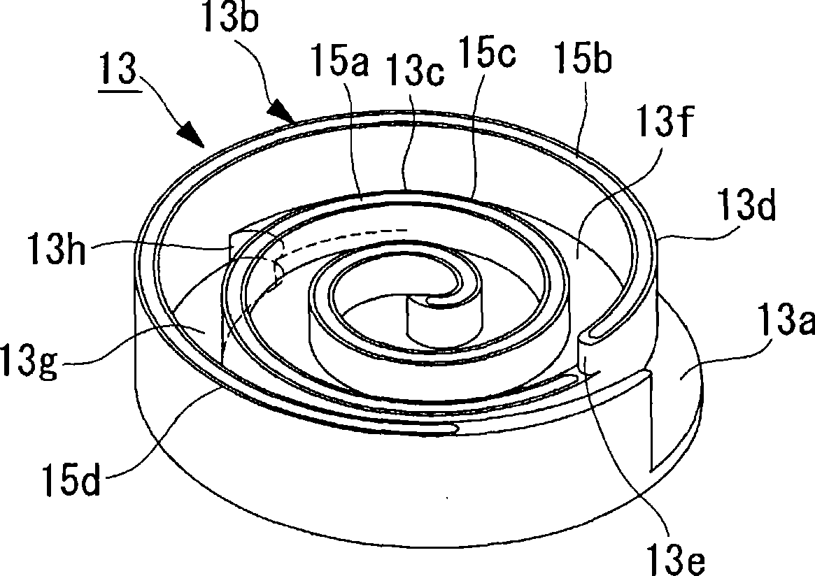
[0071] Hereinafter, the first embodiment of the present invention is used Figure 1 to Figure 4 Be explained.
[0072] figure 1 A partial longitudinal sectional view of the scroll compressor S is shown in . The scroll compressor S is a hermetic scroll compressor S having a hermetic casing 1, and an exhaust cover 2 is provided inside the hermetic casing 1 to divide the interior of the hermetic casing 1 into a high-pressure chamber HR and a low-pressure chamber LR. . A compression mechanism 3 and an electric motor 8 are provided on the low-pressure chamber LR side, and a suction pipe 6 is connected thereto. In addition, a discharge pipe 7 is connected to the side of the high-pressure chamber HR.
[0073] The compression mechanism 3 in the low-pressure chamber LR is arranged on a frame 5 fixedly arranged in the airtight casing 1 . The compression mechanism 3 is connected to the electric motor 8 through a crankshaft 9 supported by the frame 5 and the lower frame 4 via bearing...
no. 2 approach
[0099] Next, for the second embodiment of the present invention, use Figure 5 Be explained.
[0100] This embodiment differs from the above-mentioned first embodiment in that the height (wrap height) of the front end surfaces of the spiral wraps 12b, 13b is changed stepwise. Other points are the same as those of the first embodiment, and thus description thereof will be omitted.
[0101] In the above-mentioned first embodiment, the heights of the front end surfaces 12c and 12d and the front end surfaces 13c and 13d are changed in stages at fixed step differences δo and δi (δo=δi), respectively, but in this embodiment, each The step difference δi1 of the inner peripheral side front end surfaces 12c, 13c of the stepped portions 12e, 13e of the spiral wraps 12b, 13b is larger than the step difference δo of the outer peripheral side front end surfaces 12d, 13d (δo<δi1).
[0102] As described above, by making the step difference δi1 of the front end faces 12c, 13c on the inner p...
no. 3 approach
[0105] Next, for the third embodiment of the present invention, use Figure 6 Be explained.
[0106] This embodiment differs from the above-mentioned first and second embodiments in that the height of the front end surfaces of the spiral wraps 12b, 13b (wrap height) is changed stepwise. The other points are the same as those of the first and second embodiments, and thus description thereof will be omitted.
[0107] In the present embodiment, the front end faces 12d and 13d on the outer peripheral side are changed in height step by step with a constant step difference δo, but the front end portions 12c and 13c on the inner peripheral side are directed toward the center side, and the step differences δi2, δi3, and δiN are gradually changed. Increase (δi2<δi3<δiN).
[0108] As described above, by gradually increasing the steps δi2, δi3, and δiN of the front end surfaces 12c and 13c on the inner peripheral side toward the center (δi2<δi3<δiN), the inner peripheral side can be gr...
PUM
 Abstract
Description
Claims
Application Information
 - R&D
- Intellectual Property
- Life Sciences
- Materials
- Tech Scout
- Unparalleled Data Quality
- Higher Quality Content
- 60% Fewer Hallucinations
Browse by: Latest US Patents, China's latest patents, Technical Efficacy Thesaurus, Application Domain, Technology Topic, Popular Technical Reports.
© 2025 PatSnap. All rights reserved.Legal|Privacy policy|Modern Slavery Act Transparency Statement|Sitemap|About US| Contact US: help@patsnap.com


