Knee joint prosthesis system capable of controlling rigidity

A knee joint prosthesis and knee joint technology, applied in the direction of artificial legs, etc., can solve problems such as uncontrollable stiffness and poor stability

Inactive Publication Date: 2009-06-10
SICHUAN UNIV
View PDF3 Cites 12 Cited by
  • Summary
  • Abstract
  • Description
  • Claims
  • Application Information

AI Technical Summary

Problems solved by technology

In order to improve the stability and contact area of ​​the knee prosthesis system, many studies have been carried out on the matching shape of the articular surface of the femoral prosthesis and tibial prosthesis. The articular surface of the condyle is highly matched, the contact area is large, and the stability is high. In the US patent US6846329, the articular surface of the femoral prosthesis and the tibial prosthesis are designed according to the spiral surface matching, and the femoral prosthesis and the tibial prosthesis are also realized. The height of the articular surface of the condyle inside and outside the body matches, the contact area is large, and the stability is also high. However, the materials of the femoral prosthesis involved in these patents are all metal alloy materials, and their stiffness is uncontrollable. While the bone condyle articular surface of the joint prosthesis system is highly matched, it will limit the bending angle of the knee prosthesis system. In US Pat. No. 7,094,259, the knee prosthesis system can achieve deep flexion. Mismatched condylar articular surfaces, poor stability

Method used


Image

  • Knee joint prosthesis system capable of controlling rigidity

Examples


Embodiment Construction

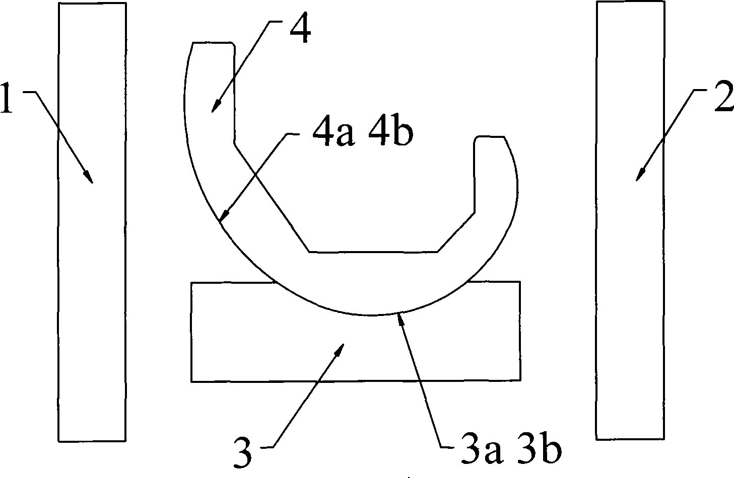
[0015] In the accompanying drawings, both the left coil 1 and the right coil 2 are fixed outside the knee joint of the human body, and the current value passing through the left coil 1 and the right coil 2 can be controlled outside the human knee joint to change the distance between the left coil 1 and the right coil 2. magnetic field value. The femoral prosthesis 4 is made of magnetorheological elastomer material, connected with the distal end of the femur (not shown) through a femoral mounting stem (not shown), and has an inner condyle 4a and an outer condyle 4b. The tibial prosthesis 3 is made of ultra-high molecular weight polyethylene, connected to the proximal end of the tibia (not shown) through a tibial mounting stem (not shown), and has an inner condyle 3a and an outer condyle 3b.

[0016] In the accompanying drawings, the femoral prosthesis 4 and the tibial prosthesis 3 are located between the left coil 1 and the right coil 2. Controlling the current value passing th...


PUM


Abstract

The invention provides a rigidity-controllable knee joint prosthesis system comprising a femur prosthesis connected with a femur far end and composed of magnetorheological elastomeric materials, a tibiae prosthesis connected with a tibiae near end and a left coil and a right coil fixed on knee joint in vitro. When controlling the current values through the left coil and the right coil on the exterior of the human body knee joint, the rigidity value of the femur prosthesis composed of magnetorheological elastomeric materials can be changed correspondingly based on the magnetic field values between the left coil and the right coil, during the knee joint prosthesis extends and bends, the femur prosthesis rigidity value is reduced, the femur prosthesis can change the shapes of inner and outer bone condyle articular surfaces according to the applied composite force inside of the knee joint prosthesis system to implement the maximum matching with the tibiae prosthesis inner and outer bone condyle articular surfaces, simultaneously, the bending degree of the knee joint prosthesis system is not limited, when the knee joint prosthesis system completes the extending and the bending motions, the femur prosthesis rigidity value is increased, the stabilities of the knee-extending position and knee-bending position can be implemented.

Description

technical field [0001] The present invention relates to a medical artificial joint, in particular to a knee joint prosthesis system applied to the human body, which is used to replace the human body's natural knee joint which has lost all or part of its function due to pathological changes or injuries during knee arthroplasty. . Background technique [0002] The development of the knee prosthesis system has a history of more than 40 years. When the human body's natural knee joint loses all or part of its function due to disease or injury, it needs to be replaced with a knee joint prosthesis system to reconstruct the knee joint. To maintain normal function and relieve the patient's pain, the implementation of knee prosthesis system replacement can achieve the best therapeutic effect and restore the patient's mobility to the greatest extent. [0003] Commonly referred to as the knee prosthesis system includes two major parts of the femoral prosthesis and the tibial prosthesis...

Claims


Application Information

Patent Timeline
Patent Type & Authority Applications(China)
IPC IPC(8): A61F2/64
Inventor 张国亮姚进裴福兴周宗科
Owner SICHUAN UNIV
Why Eureka
Try Eureka