Laser driver and temperature compensation circuit thereof

A temperature compensation circuit and laser driver technology, applied in the field of optical communication, can solve the problems of energy consumption, large area, occupation, etc., and achieve the effect of strong temperature adaptability and elimination of influence

Inactive Publication Date: 2009-06-10
JIANGNAN INST OF COMPUTING TECH
View PDF4 Cites 49 Cited by
  • Summary
  • Abstract
  • Description
  • Claims
  • Application Information

AI Technical Summary

Problems solved by technology

However, the use of cooling systems or refrigerators will occupy a large area and consume extra energy, whic

Method used


Image

  • Laser driver and temperature compensation circuit thereof
  • Laser driver and temperature compensation circuit thereof
  • Laser driver and temperature compensation circuit thereof

Examples


Embodiment Construction

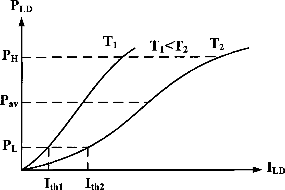
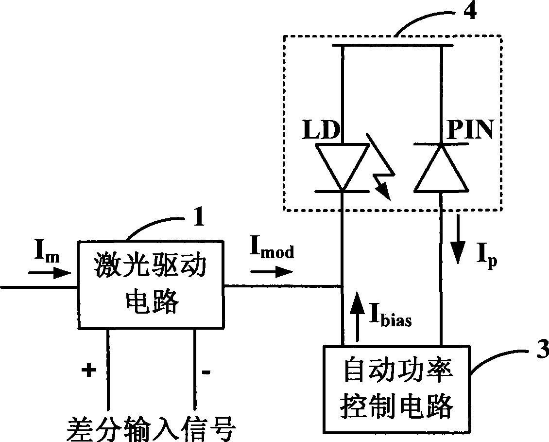
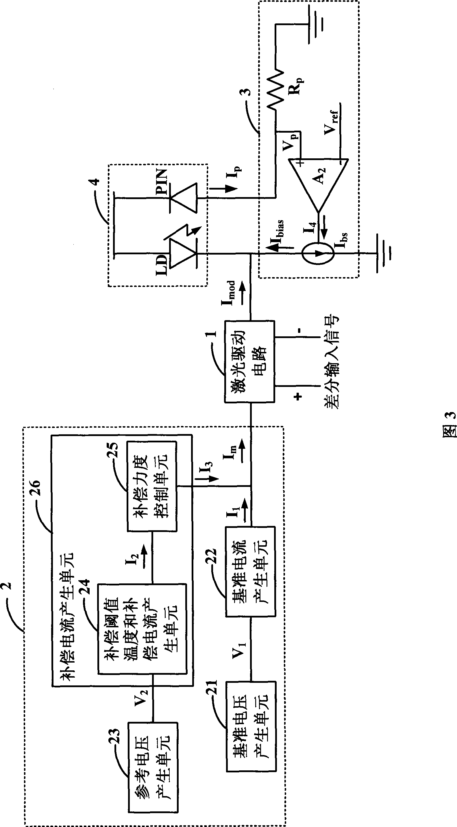
[0057] In the embodiment of the present invention, the modulation current of the laser is compensated by the temperature compensation circuit so that the output optical signal of the laser has a constant extinction ratio, and the bias current of the laser is compensated by the bias current adjustment circuit so that the laser can obtain stable output optical power. The specific implementation of the present invention will be described in detail below in conjunction with the accompanying drawings and embodiments.

[0058] The basic structure of the temperature compensation circuit of the laser driver of the embodiment of the present invention is shown in Figure 3, the temperature compensation circuit 2 includes: a reference voltage generation unit 21, a reference current generation unit 22, a reference voltage generation unit 23 and a compensation current generation unit 26.

[0059] The reference voltage generation unit 21 generates a reference voltage V that increases with te...


PUM


Abstract

The invention discloses a laser driver and a temperature compensation circuit thereof. The temperature compensation circuit comprises a benchmark voltage generation unit, a benchmark current generation unit, a reference voltage generation unit, and a compensation current generation unit, wherein the benchmark voltage generation unit generates a benchmark voltage which increases with the increase of the temperature; the benchmark current generation unit is connected with the benchmark voltage generation unit and outputs benchmark current which increases with the increase of the benchmark voltage; the reference voltage generation unit generates a reference voltage which increases with the increase of the temperature; the compensation current generation unit is connected with the reference voltage generation unit, obtains the compensation threshold temperature according to the reference voltage, and outputs compensation current when the temperature is higher than or equal to the compensation threshold temperature; and the benchmark current and the compensation current are overlapped to form benchmark modulation current. The laser driver comprises the temperature compensation circuit and a bias current regulation circuit. An optical signal output by the laser can have constant extinction ratio by compensating modulation current of a laser through the temperature compensation circuit, and the laser can obtain steady output optical power by compensating bias current of the laser through the bias current regulation circuit.

Description

technical field [0001] The invention relates to optical communication technology, in particular to a laser driver and a temperature compensation circuit thereof. Background technique [0002] In the optical communication system, the semiconductor laser and the laser driver (LDD, Laser Diode Driver) are the key components of the optical transmitter, in which the laser driver amplifies the high-speed digital signal output by the serial converter or the multiplexer, and outputs the drive The driving current required by the laser, the driving current output by the laser driver (that is, the current of the laser) includes the modulation current and the DC bias current. [0003] The performance of lasers is characterized by parameters that vary with temperature, such as figure 1 The optical power-current curve of the laser diode (LD, Laser Diode) shown, the laser diode output optical power P L ~P H The laser can be generated within the range, as the temperature increases (T 1 ...

Claims


Application Information

Patent Timeline
IPC IPC(8): H04B10/155H03K17/687H04B10/564
Inventor 高剑刚刘杰金利锋邬宁彪徐永法徐江川袁爱东吴新军腾志刚
Owner JIANGNAN INST OF COMPUTING TECH
Why Eureka
Try Eureka