Mounting structure of steering wheel central bush

A technology of installation structure and steering wheel, which is applied to steering control, handwheel and other directions installed on the car, can solve problems such as deformation, and achieve the effects of low cost, easy processing and manufacturing, and low material price.

Inactive Publication Date: 2009-06-17
THIXOMAG TECHNOLOGH WUHU
View PDF0 Cites 1 Cited by
  • Summary
  • Abstract
  • Description
  • Claims
  • Application Information

AI Technical Summary

Problems solved by technology

[0010] The problem to be solved by the present invention is to provide a steering wheel center bush installation structure, the purpose of which is to solve the deformation problem of the inner taper of the bearing sleeve of the steering wheel during die casting

Method used


Image

  • Mounting structure of steering wheel central bush
  • Mounting structure of steering wheel central bush
  • Mounting structure of steering wheel central bush

Examples


Embodiment 1

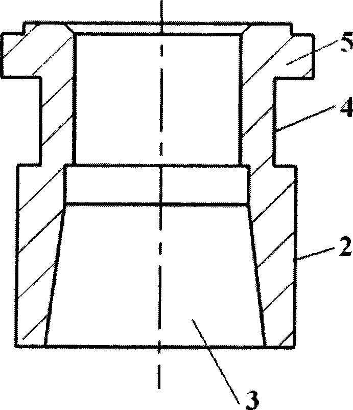
[0031] Between the end boss 5 and the middle boss 7 of the present invention is an annular groove 4; the outer circle from the middle boss 7 to the end of the tapered hole 3 is the outer circle 7 of the tapered hole; The diameter of the groove 4 is equal to the diameter of the outer circle 7 of the tapered hole.

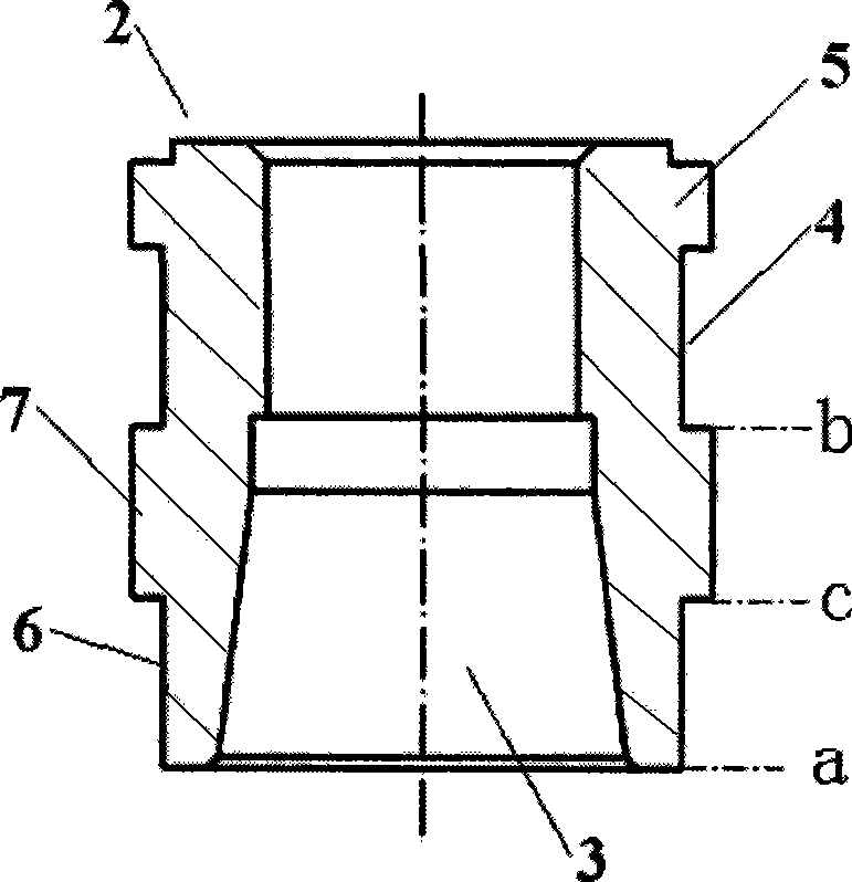
[0032] From figure 2 It can be seen from the figure that the cross-sectional shape and size of the steering wheel center bushing 2 change: increasing the wall thickness of the groove 4 on the steering wheel center bushing 2 not only effectively increases the stiffness at the cylindrical hole of the steering wheel center bushing 2, but also improves The thermal stress distribution state at the groove 4 is shown.

Embodiment 2

[0034] Such as figure 2 As shown, the intermediate boss 7 of the present invention is located on the end face of the groove 4 direction, and the distance to the end of the tapered hole 3 is ab; the axial dimension of the intermediate boss 7 is bc ; said bc:ab=0.618:1.

[0035] Applying the "golden section" idea, the length of the thickening zone based on the boss is taken as 0.618 of the axial projection of the cone surface, and the thickness of the BUSH section at this place is increased to be equal to the diameter at position 1; figure 2 At the point b shown, taking point b as the base, take bc as the axial thickening zone of the steering wheel center bushing 2, and bc=0.618ab (that is, the golden section point). From figure 2 It can be seen from the structural diagram that increasing the section thickness of the inner bearing sleeve 2 not only effectively increases the stiffness of the section of the inner bearing sleeve 2, but also improves the thermal stress distribu...

Embodiment 3

[0037] During die-casting production, the specific implementation plan is:

[0038] 1. Cut out 45 steel materials and process the embedded bearing kit with machine tools;

[0039] 2. Put the processed inner bearing sleeve into the inlay position of the die-casting mold, and position it as an inner insert;

[0040] 3. Close the die-casting mold and pour the magnesium alloy melt;

[0041] 4. Die-casting production of steering wheel parts.

[0042] For the steering wheel produced by die-casting according to the present invention, the tapered bonding surface of the embedded steering wheel center bushing 2 can meet the testing requirements of the tapered bonding by 100% with the tapered testing tool. This technological method for solving the deformation of the tapered surface of the automobile steering wheel bearing sleeve has obvious engineering value because it is practical and simple, and can be completely solved by one-time die casting.


PUM

PropertyMeasurementUnit
tensile strengthaaaaaaaaaa
elongationaaaaaaaaaa

Abstract

The invention discloses a structure for mounting a central liner of a steering wheel. The structure is provided with two steps; and one is an end part lug boss (5) positioned at one end of a cylindrical hole of a bearing sleeve (2) of the steering wheel, and the other one is a middle lug boss (7) axially positioned on an outer circle at the smallest aperture part of a taper hole (3). With the technical proposal, the structure solves the problem of deformation when an inner taper of the bearing liner of the steering wheel is subjected to die casting, is simple and convenient to implement and improves production efficiency.

Description

technical field [0001] The invention belongs to the technical field of auto parts structure, and relates to an auto power control system, more specifically, the invention relates to a steering wheel center bush installation structure. Background technique [0002] At present, the car steering wheel bracket has become one of the parts made of light alloy. In the forming process of aluminum alloy and magnesium alloy, casting is mainly used. For parts that require wear resistance, the method of embedding other wear-resistant materials is usually used inside. Among them, steel parts are mainly embedded in parts that require wear resistance. [0003] The modern car steering wheel made of aluminum-magnesium alloy has the characteristics of light weight, small deformation and beautiful appearance. mostly used as image 3 Steering wheel shown. The material of the steering wheel is aluminum alloy and magnesium alloy with high elongation rate. Magnesium alloy materials such as AM60...

Claims


Application Information

Patent Timeline
Patent Type & Authority Applications(China)
IPC IPC(8): B62D1/10B22D19/00
Inventor 徐章跃黄海吴仁荣张建军
Owner THIXOMAG TECHNOLOGH WUHU
Why Eureka
Try Eureka