Eureka AIR delivers breakthrough ideas for toughest innovation challenges, trusted by R&D personnel around the world.

Reticule thickness measuring instrument

A tester and marking technology, applied in the field of marking thickness tester, can solve the problems of large human error, troublesome operation, large error in test accuracy, and achieve the effect of reducing confusion and potential safety hazards, easy operation and high precision

Inactive Publication Date: 2009-06-17
朱建新
View PDF0 Cites 5 Cited by
  • Summary
  • Abstract
  • Description
  • Claims
  • Application Information

AI Technical Summary

Problems solved by technology

[0002] In today's society, the traditional marking line thickness test uses calipers, feeler gauges, and even manual measurement methods such as the coin comparison method. The test accuracy is poor, the operation is troublesome, and the human error is large, and it is impossible to detect whether the road surface is qualified.
Due to the inability to accurately detect, some markings are too thin to be used for a period of time, and they will wear off, which will cause road traffic chaos, pose safety hazards, and slow down the development of modernization.
Due to the above shortcomings, the existing equipment and measurement methods can no longer adapt to the quality control of construction, on-site supervision of supervision, and acceptance of projects, let alone the needs of road maintenance and construction

Method used


Image

  • Reticule thickness measuring instrument
  • Reticule thickness measuring instrument
  • Reticule thickness measuring instrument

Examples


Embodiment 1

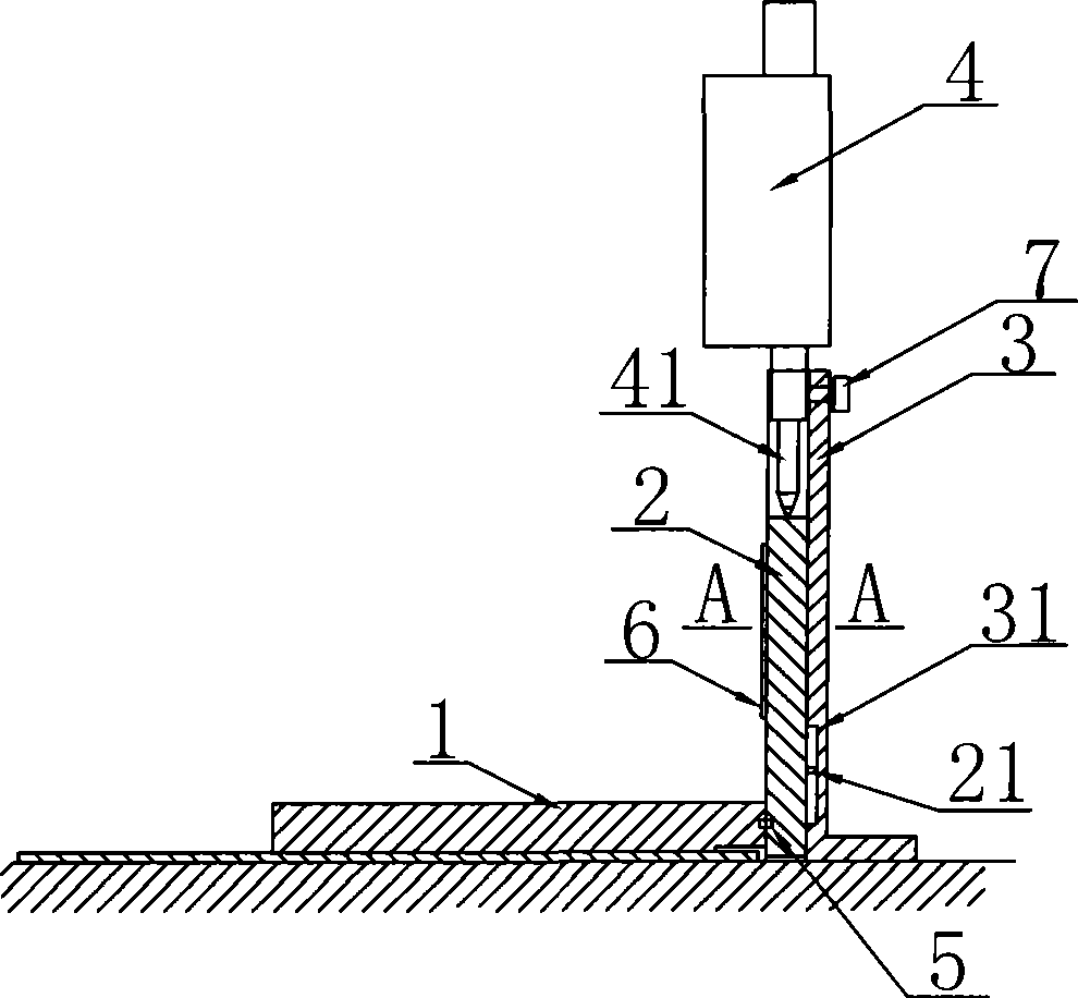
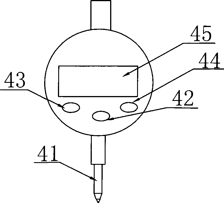
[0018] Such as figure 1 , figure 2 , Figure 5 It is the first embodiment of a marking line thickness tester of the present invention, including a movable measuring platform 1, a sliding column 2, a column 3, and a high-precision measuring gauge 4, and the high-precision measuring gauge 4 is a high-precision digital display dial indicator , the movable measurement platform 1 is connected to the side wall of the sliding column 2, a chute is provided in the column 3, the sliding column 2 is arranged in the chute, the high-precision measuring table 4 is fixed on the column 3, and the high The measuring head 41 of the accuracy measuring table is in close contact with the column head of the sliding column 2, and the movable measuring platform 1 and the sliding column 2 are flexibly connected through a rotating device; the rotating device is a hinge pin 5, and the chute in the column 3 The cross section is rectangular, and the sliding column 2 is compatible with the chute, and th...

Embodiment 2

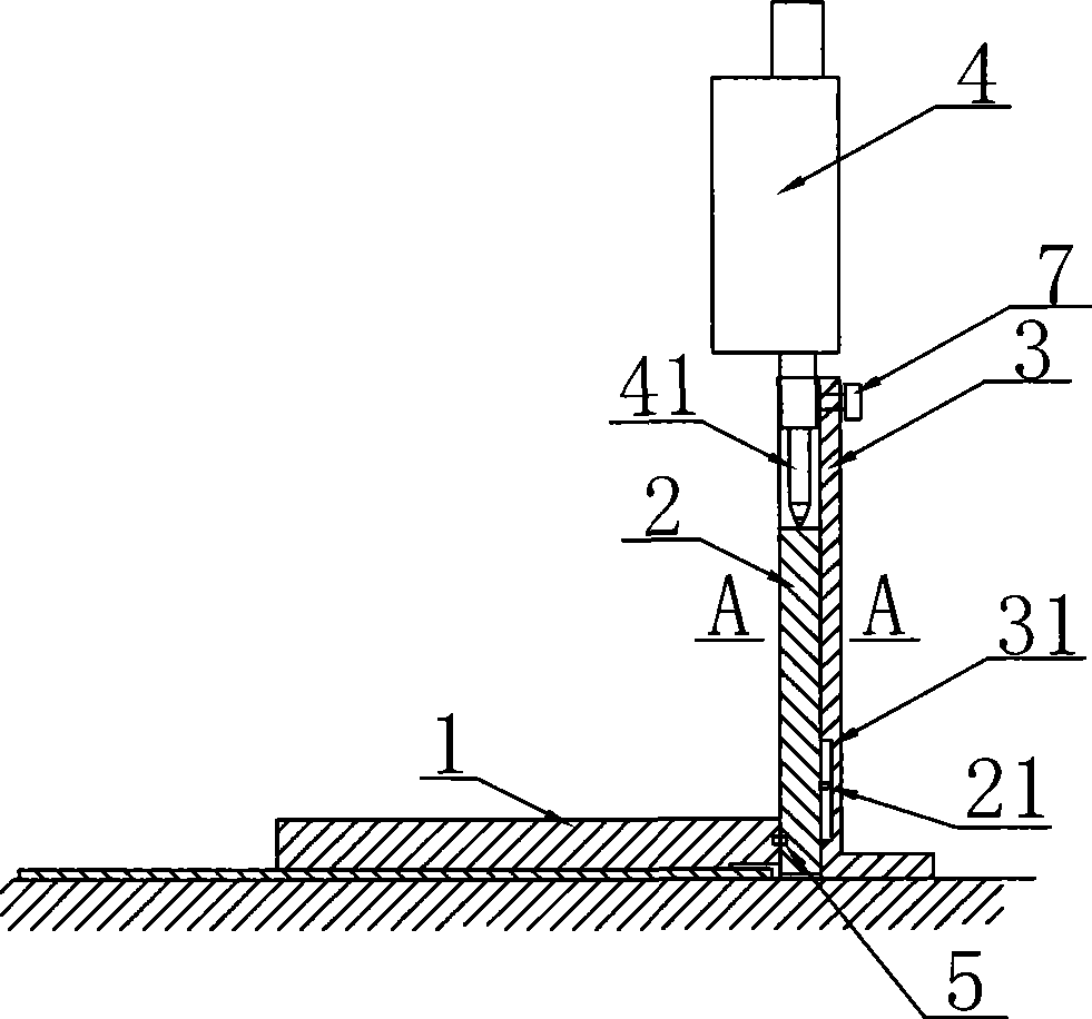
[0021] Such as image 3 , Figure 4 , Figure 5 It is the first embodiment of a marking line thickness tester of the present invention, including a movable measuring platform 1, a sliding column 2, a column 3, and a high-precision measuring gauge 4, and the high-precision measuring gauge 4 is a high-precision digital display dial indicator , the movable measurement platform 1 is connected to the side wall of the sliding column 2, a chute is provided in the column 3, the sliding column 2 is arranged in the chute, the high-precision measuring table 4 is fixed on the column 3, and the high The measuring head 41 of the accuracy measuring table is in close contact with the column head of the sliding column 2, and the movable measuring platform 1 and the sliding column 2 are flexibly connected through a rotating device; the rotating device is a hinge pin 5, and the chute in the column 3 is The dovetail groove, the sliding column 2 is matched with the sliding channel, the sliding c...


PUM


Abstract

The invention discloses a tester for the thickness of a marked line. The tester comprises a movable measuring platform, a sliding post, a vertical post and a high-accuracy measuring meter. The movable measuring platform is connected with the lateral wall of the sliding post; a sliding groove is arranged in the vertical post and the sliding post is arranged in the sliding groove; and the high-accuracy measuring meter is fixed on the vertical post, and the measuring head of the high-accuracy measuring meter is tightly contacted with the post head of the sliding post. The invention has the advantages of simple operation, high accuracy and tiny error. The tester provides convenience to the quality control of the construction, the field management of the supervision and the acceptation of the project. The tester is suitable for the maintenance and construction of the modern road and reduces the disturbance and the potential safety hazard for the urban traffic.

Description

technical field [0001] The invention relates to a road surface measuring device, in particular to a marking line thickness tester. Background technique [0002] In today's society, the traditional marking line thickness test uses calipers, feeler gauges, and even manual measurement methods such as the coin comparison method. The test accuracy is poor and the error is large, the operation is troublesome, and the human error is large, and it is impossible to detect whether the road surface is qualified. Due to the inability to accurately detect, some markings are too thin and worn out after being used for a period of time, which will cause road traffic chaos, have potential safety hazards, and slow down the development of modernization. Due to the above shortcomings, the existing equipment and measurement methods can no longer meet the quality control of construction, on-site supervision of supervisors, and acceptance of projects, let alone the needs of road maintenance and co...

Claims


Application Information

Patent Timeline
Patent Type & Authority Applications(China)
IPC IPC(8): E01C23/01
Inventor 朱建新
Owner 朱建新
Why Eureka
Eureka Blog
Learn More