Solution pressure transformation desorption/compressing refrigeration cycle apparatus

A compression refrigeration and circulation device technology, which is applied in the direction of refrigerators, compressors, refrigeration components, etc., can solve the problems that the refrigeration effect is difficult to improve, and achieve the effects of avoiding adverse effects, improving refrigeration coefficient, and high unit cooling capacity

Inactive Publication Date: 2010-07-21
OCEAN UNIV OF CHINA
View PDF0 Cites 0 Cited by
  • Summary
  • Abstract
  • Description
  • Claims
  • Application Information

AI Technical Summary

Problems solved by technology

[0004] The purpose of the present invention is to overcome the defect that the refrigeration effect of the existing vapor compression refrigeration cycle device is difficult to improve, and propose a solution pressure swing desorption-compression refrigeration cycle device, which uses the solution to desorb in a low pressure generator at isothermal pressure The refrigeration capacity is generated, and the refrigeration capacity per unit working fluid is much higher than that of traditional evaporative refrigeration. By controlling the pressure and pressure changes of the solution, the compression work of the refrigerant gas can be equivalent to that of the traditional vapor compression refrigeration cycle, thereby obtaining a higher refrigeration coefficient.

Method used


Image

  • Solution pressure transformation desorption/compressing refrigeration cycle apparatus
  • Solution pressure transformation desorption/compressing refrigeration cycle apparatus
  • Solution pressure transformation desorption/compressing refrigeration cycle apparatus

Examples


Embodiment 1

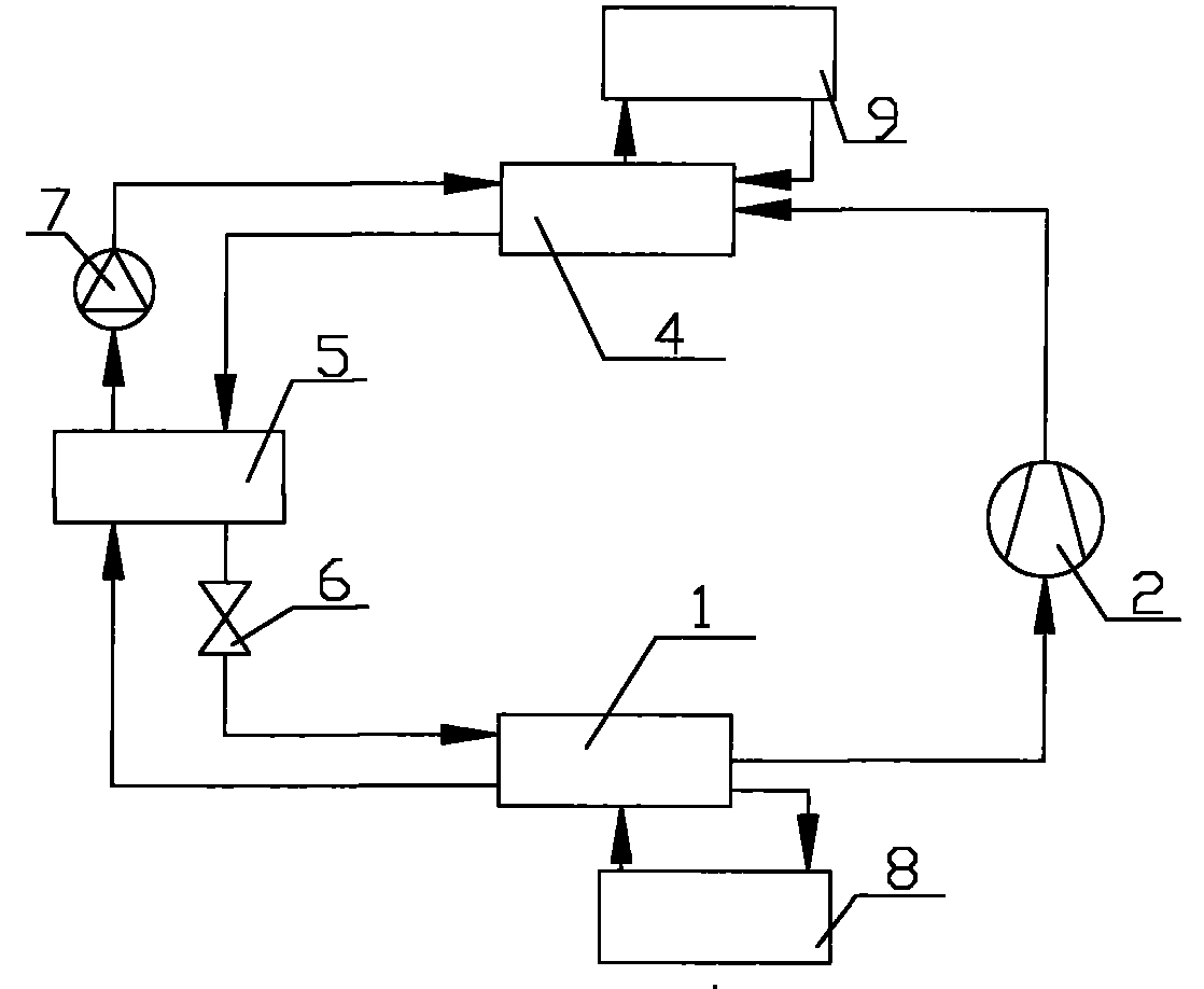
[0027] like figure 1 As shown, the refrigeration cycle device includes a low-pressure generator 1, a compressor 2, an absorber 4, a heat exchanger 5, a throttle valve 6 and a solution pump 7, wherein an inlet of the low-pressure generator 1 passes through a pipeline and the throttle valve 6 One outlet communicates with the inlet of the compressor 2 through a pipeline, and the other outlet communicates with an inlet of the heat exchanger 5 through a pipeline. An inlet and an outlet are also provided on the low-pressure generator 1, which respectively communicate with the low-temperature heat store through pipelines. 8 exports and imports are connected. One inlet of the absorber 4 is communicated with the outlet of the compressor 2 through the pipeline, the other inlet is communicated with the outlet of the solution pump 7 through the pipeline, and one outlet is communicated with the other inlet of the heat exchanger 5 through the pipeline, and the absorber 3 is also provided wi...

Embodiment 2

[0037] like Figure 5 As shown, the horizontal spiral micro-groove tube 11 in the low-pressure generator 1 can be replaced by a wire mesh pipe 11', and a brine is introduced into the wire mesh pipe 11' to take away the cold energy, and the ammonia water entering from the ammonia water inlet is in the wire mesh pipe 11'. Rising film desorption is performed on the network pipe 11' to release ammonia vapor.

[0038] Others are with embodiment 1.

Embodiment 3

[0040] like Figure 6 As shown, the cross-sectional shape of the gas channel 12 at the top of the horizontal spiral microgroove tube 11 and the solution channel 13 at the bottom of the horizontal spiral microgroove tube 11 in the low-pressure generator 1 are sloped, and the slope can play a role in reducing pressure, realizing The generation process of concentrated ammonia solution under isothermal and variable pressure. In order to make the pressures on the same section of the low-pressure generator equal, the slope of the slope of the solution channel 13 is greater than the slope of the slope of the gas channel 12 .

[0041] Others are with embodiment 1.


PUM


Abstract

The invention relates to a refrigerating system, in particular to a variable pressure desorption-compression refrigeration cycle device which gasifies ammonia in water solution as refrigerant. The device comprises a low pressure generator, a compressor, a heat exchanger, a throttling device, a heat exchanger and a solution pump. The low pressure generator comprises a climbing film desorption tube, a gas channel and a solution channel. An outlet of the gas channel is communicated with an inlet of the compressor by a pipeline. An inlet of the solution channel is communicated with an outlet of the throttling device by a pipeline, and an outlet of the solution channel is communicated with an inlet of the heat exchanger. The gas channel is arranged above the climbing film desorption tube. The solution channel is correspondingly arranged under the climbing film desorption tube. The inside of the gas channel and the solution channel are respectively provided with a dropping device. The refrigerating capacity of unit refrigerant of the refrigerating system is much higher than the traditional evaporating refrigerating capacity. The solution generation pressure and pressure changes are controlled to equalize the refrigerating gas compression power with the traditional vapor compression refrigeration cycle. Therefore, higher refrigerating coefficients are obtained.

Description

technical field [0001] The invention relates to a refrigerating system, in particular to a pressure-swinging desorption-compression refrigerating cycle device which vaporizes ammonia from an aqueous solution as a refrigerant. Background technique [0002] At present, most commonly used refrigeration devices are vapor compression refrigeration cycle devices. The structure of the device is as follows: figure 1 As shown, it is mainly composed of an evaporator 1, a compressor 2, a condenser 3 and a throttling device 4. This device uses hydrocarbons or ammonia as a circulating working medium, that is, a refrigerant, and relies on the working medium in the evaporator 1 The evaporator absorbs heat to produce a cooling effect. The outlet of the evaporator 1 is connected to the inlet of the compressor 2. The steam generated by the evaporator 1 is compressed by the compressor 2 to condense it. The outlet of the compressor 2 is connected to the inlet of the condenser 3. The steam is s...

Claims


Application Information

Patent Timeline
Patent Type & Authority Patents(China)
IPC IPC(8): F25B1/00F25B35/00
CPCY02B30/64Y02A30/27Y02B30/00
Inventor 梅宁李艳丁爽刘小军
Owner OCEAN UNIV OF CHINA
Why Eureka
Try Eureka