
Three-dimensional contour outline measuring set based on multi sensors and measuring method thereof
A three-dimensional contour and multi-sensor technology, applied in the field of optical inspection, can solve the problems of low measurement efficiency of three-coordinate measuring machines, unsuitable for batch inspection of parts, unsuitable for precision parts inspection, etc.
- Summary
- Abstract
- Description
- Claims
- Application Information
AI Technical Summary
Problems solved by technology
Method used
Image

Examples
Embodiment
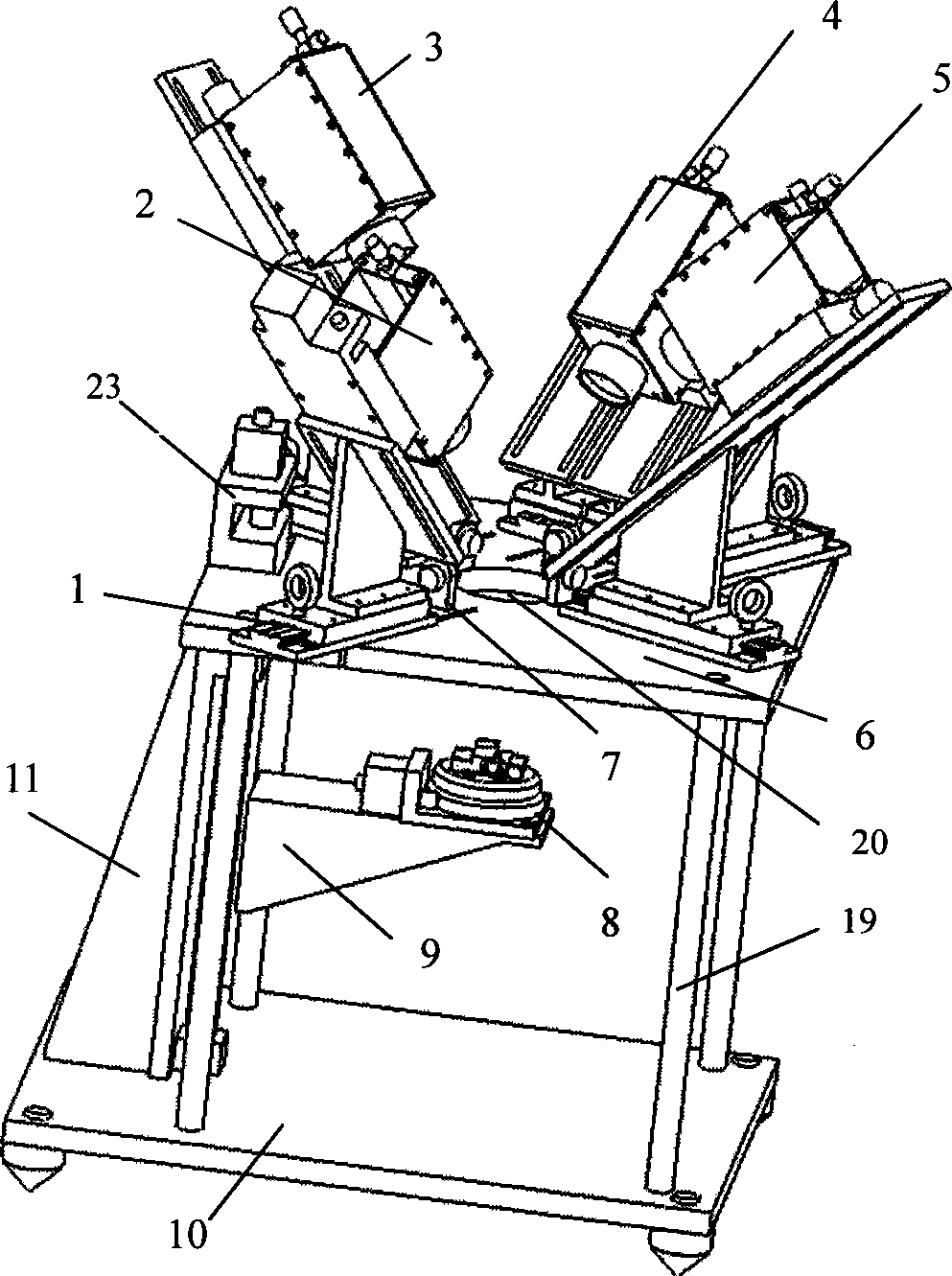
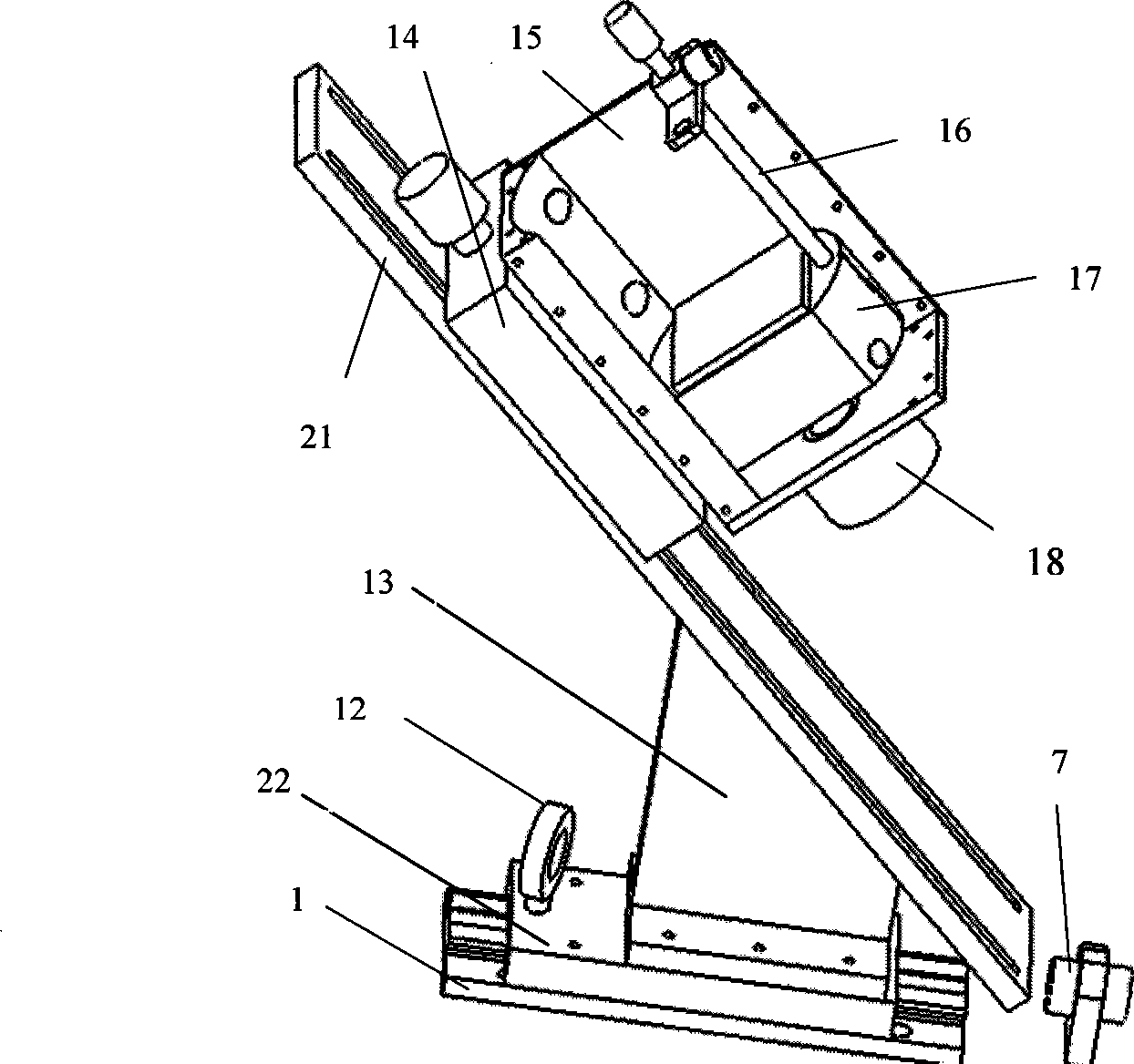
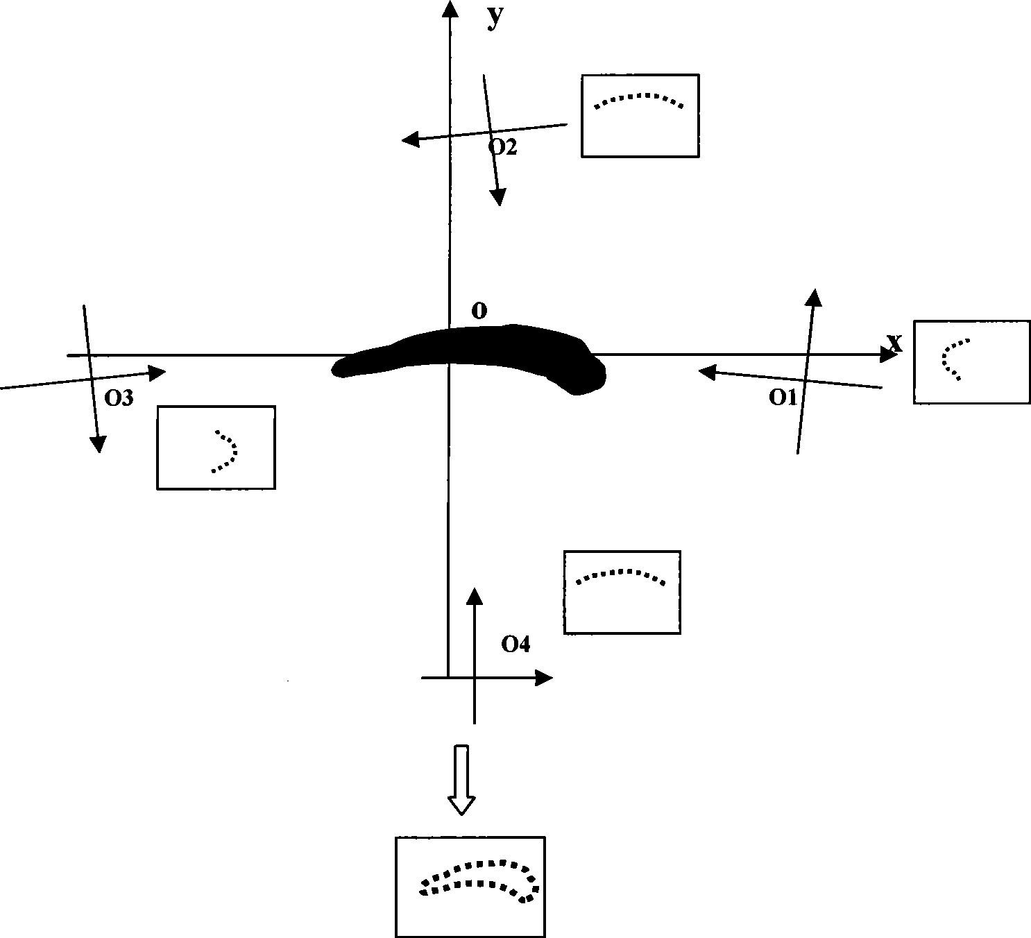
[0060] In the following, the feasibility of the present invention will be analyzed by taking the measurement of the blade profile of an aeroengine as an example. The multi-sensor-based three-dimensional profile measurement device used in this embodiment is as figure 1 A setup with four light-measuring components is shown.
[0061] 1. Before the measurement starts, the following series of preparations need to be done:
[0062] (1) First adjust the four lasers 7 in the same plane. The specific implementation method is to use the vertical screen to receive the light knives emitted by any two lasers 7. When the receiving screen moves from far to near and from near to far, the two The light knives are always displayed as being on a straight line, at this time we think that the two light knives are already in the same horizontal plane, that is, the laser 7 is also in the same horizontal plane;
[0063] (2) Clamping the aeroengine blade on the fixture 8;
[0064] (3) Roughly measu...
PUM
 Abstract
Description
Claims
Application Information