Vortex optical gyro

A technology of vortex light and gyroscope, applied in the field of vortex light gyroscope

Active Publication Date: 2016-11-09
任元
View PDF4 Cites 8 Cited by
  • Summary
  • Abstract
  • Description
  • Claims
  • Application Information

AI Technical Summary

Problems solved by technology

At present, it is the first public proposal in the world to apply the inertial measurement method based on superposition vortex light to the field of gyroscopes.

Method used


Image

  • Vortex optical gyro
  • Vortex optical gyro
  • Vortex optical gyro

Examples


Embodiment Construction

[0065] specific implementation plan

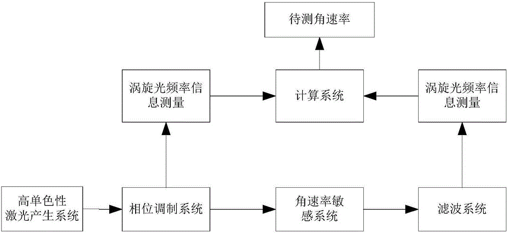
[0066] The implementation object of the present invention is an object to be measured with angular rate and posture changes, and the schematic diagram of the specific embodiment is as follows figure 1 As shown, the specific implementation steps are as follows:

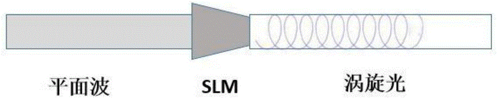
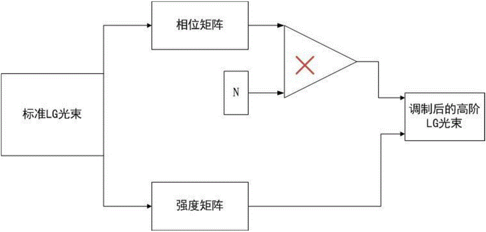
[0067] (1) Generate superposition vortex light with high-order angular momentum

[0068] Place the HG beam laser with better monochromaticity and the SLM coaxially on the rotation axis of the measured dimension of the object to be measured, such as figure 1 As shown, the wave function expression of Laguerre-Gaussian beam (referred to as LG beam) is:

[0069]

[0070] In the formula, is the Laguerre-Gaussian polynomial, l is the topological charge representing the orbital angular momentum, p represents the proportion of each component, Z represents the phase of light, is the beam width, is the Laguerre polynomial, r is the radius of the laser cavity, z R =kω 2 0 / 2 r...


PUM


Abstract

The invention relates to a vortex optical gyro. Firstly, with a method using phase modulation according to a vortex light wave function, coupling-state vortex light composed of vortex light having opposite wave front spiral directions and having the orbital angular momentum topological charges of +1 and -1 respectively is generated; according to a sagnac effect, synchronous rotation of a coupling-state vortex light generation system and a to-be-measured object is known to make two beams of vortex light having opposite wave front spiral directions generate an optical path difference related to the rotation speed of the to-be-measured object; the specificity of the vortex light makes the optical path difference reflected in angular frequency movement; an optical path of the vortex light is adjusted to change the propagation direction, then through modulated filtration, the vortex light is received, and a waveform of the vortex light is measured; and through waveform analysis, the angular frequency movement of the superposition-state vortex light is obtained, and angular velocity information of the to-be-measured object is calculated. The vortex optical gyro belongs to the field of new-concept gyro in the inertial technology, and can be applied in the fields of superhigh-sensitivity and miniaturized navigation and positioning in future.

Description

technical field [0001] The invention relates to a vortex optical gyroscope. technical background [0002] As an autonomous navigation system, the inertial navigation system has the advantages of all-weather, full-time and space-time, good concealment, not easy to be interfered, unable to be reversed and strong survivability compared with the satellite navigation system, but as a dead reckoning navigation system , the gyroscope error will cause its navigation parameter error to accumulate rapidly with time, that is, the navigation accuracy diverges with time, and the long-term stability is poor. Therefore, the gyroscope is the core of the inertial navigation system and the main bottleneck restricting the accuracy of inertial navigation. In response to the needs of future space activities, due to the continuous improvement of flight distance, flight time, and flight speed, higher and higher requirements are placed on the accuracy, sensitivity, and volume of navigation equipme...

Claims


Application Information

Patent Timeline
Patent Type & Authority Applications(China)
IPC IPC(8): G01C19/64
CPCG01C19/64
Inventor 任元王刚谢璐刘政良李基
Owner 任元
Why Eureka
Try Eureka