Optical module

A technology of optical modules and optical fibers, applied in the field of optical modules, can solve problems such as difficulty in ensuring yield rate and difficulty in yield rate

Inactive Publication Date: 2009-06-17
HITACHI LTD
View PDF1 Cites 13 Cited by
  • Summary
  • Abstract
  • Description
  • Claims
  • Application Information

AI Technical Summary

Problems solved by technology

It is difficult to ensure the yield rate while requiring the positional accuracy of the wavelength demultiplexer, especially the relative angle deviation margin is small, and requires high-precision mounting.
Furthermore, when scalability is considered, the number of optical components and the mounting area need to be approximately doubled, and miniaturization and further high-precision mounting of optical components are required, so it is becoming more and more difficult to ensure yield

Method used


Image

  • Optical module
  • Optical module
  • Optical module

Examples


Embodiment 1

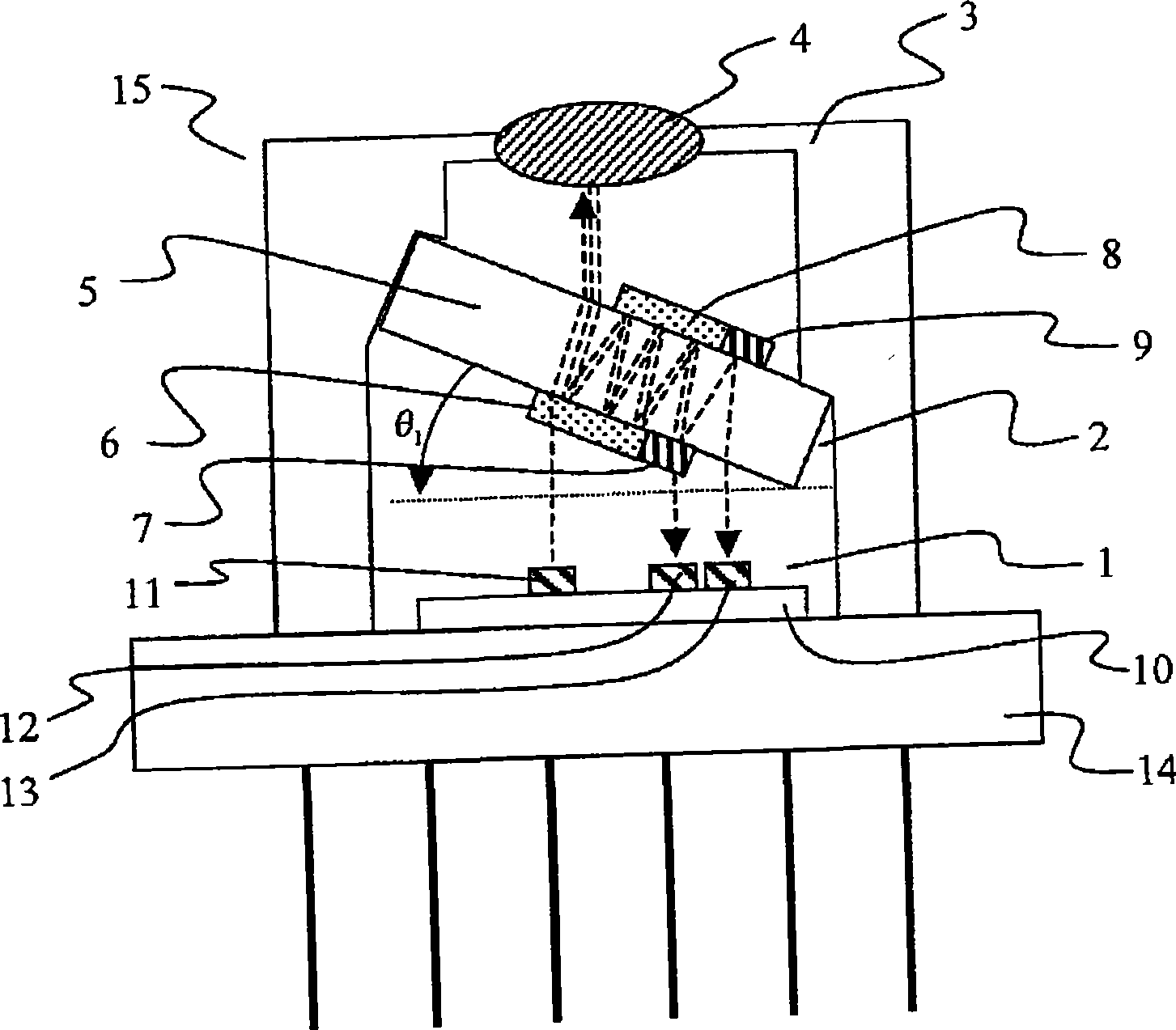
[0049] figure 1 is a cross-sectional view of an optical module as a first embodiment of the present invention. figure 1 This is an example in which the present invention is applied to a module called an optical triplexer using a three-wavelength bidirectional optical transmission and reception module.

[0050] figure 1 It is an example of mounting on a CAN package. The light-emitting element 11 and light-receiving elements 12, 13 are loaded on the base 10. The optical element loading substrate 1 is installed on the CAN socket 14, and the optical multiplexer and demultiplexer 2 is installed on the On the CAN cover 3, a triplexer module 15 is formed. The operating wavelengths of the optical elements 11, 12, and 13 are λ1, λ2, and λ3 respectively, and the length relationship of the wavelengths is λ1 figure 1 In the upper part, the elements are arranged from elements with shorter wavelengths to elements with longer wavelengths. Concave-convex for installing optical multiplex...

Embodiment 2

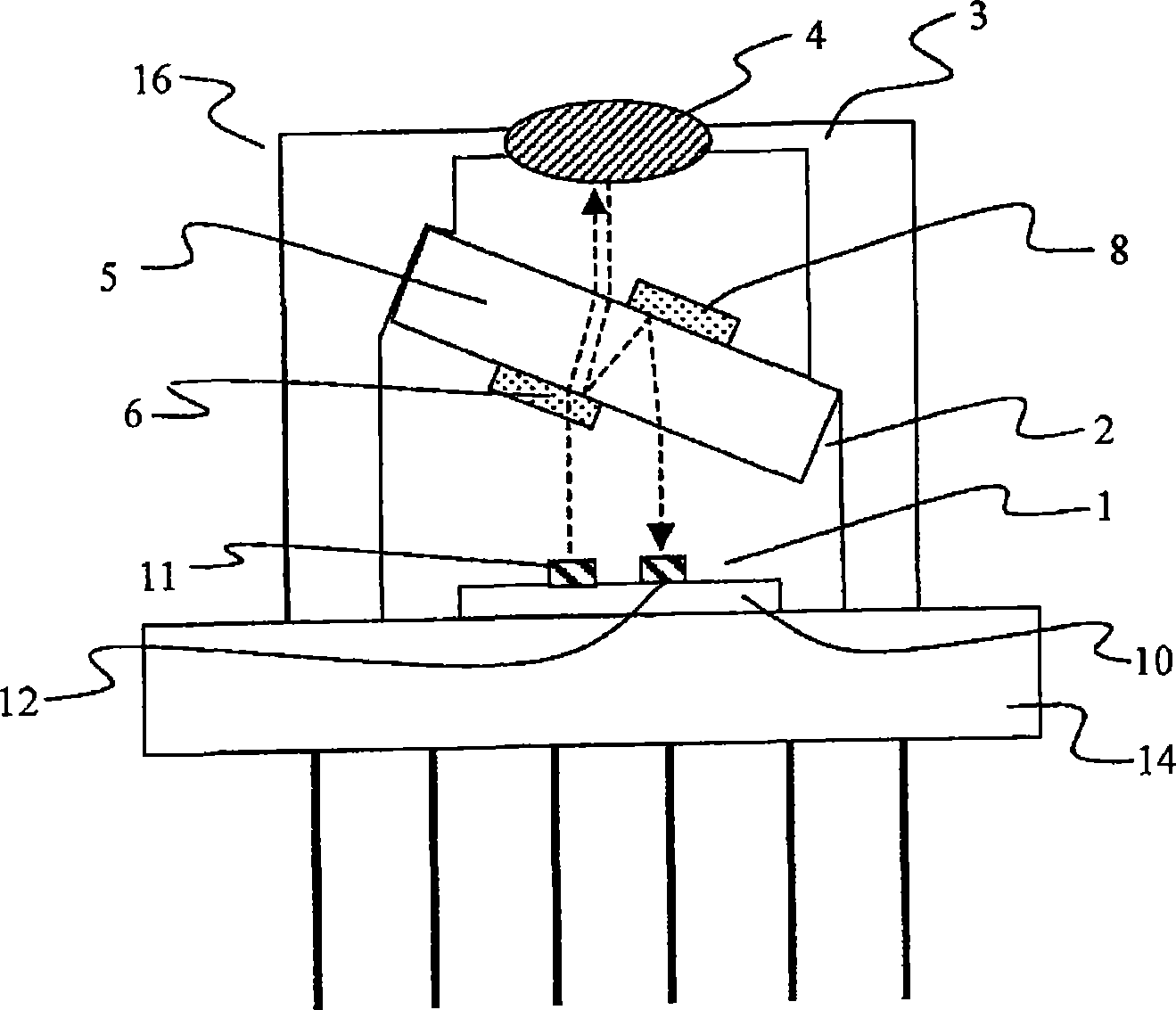
[0057] image 3 is a cross-sectional view of an optical module according to a second embodiment of the present invention. This embodiment is a configuration example in which the present invention is applied to a two-wavelength single-core bidirectional (BIDI: Bi-Directional) module. Such as image 3 As shown, the BIDI module 16 is the same as the first embodiment in that it is composed of the optical element mounting substrate 1 , the wavelength multiplexer / demultiplexer 2 and the CAN package 3 . However, since the BIDI module transmits and receives at two wavelengths, one upstream wavelength and one downstream wavelength, the only optical elements mounted on the optical element mounting substrate 1 are the light emitting element 11 and the light receiving element 12 . On the optical multiplexer / demultiplexer 2, one type of optical filter 6 and mirror 8 are respectively installed.

Embodiment 3

[0059] Figure 4 is a cross-sectional view of an optical module according to a third embodiment of the present invention. This embodiment is an example in which the present invention is applied to a so-called pigtail type module with optical fibers. Such as Figure 4 As shown, the triplexer module 15 of the first embodiment of the present invention is installed on the coaxial square module housing 21 , and an optical fiber 22 with a ferrule is further installed through a sleeve (sleeve) 23 . In this example, an example of a pigtail type module is shown, but a removable type (resectable) module can also be configured with the same structure.


PUM


Abstract

A problem to be solved by the invention is to provide an optical module cheaper than the prior art. The invention provides an optical module comprising: a pedestal arranged on a CAN tube seat; at least a first light-emitting element and a first light-receiving element having different wavelength and arranged on one surface of the pedestal; a CAN cap fixed on the pedestal and having holes for light; and a parallel flat optical multiplexer having a first wavelength selective filter on one surface of the pedestal that has transmissivity to passing light and a mirror on the other surface. An extending direction of the optical multiplexer is fixed in the CAN cap or the package being tilted by an angle with respect to one surface of an optical element mounting board. Outgoing light from the first light-emitting element passes through the wavelength selective filter and the pedestal and enters an optical fibre outside the cap, and outgoing light from the optical fibre enters the optical multiplexer and is reflected by the wavelength selective filter and further reflected by the mirror, and then exits the optical multiplexer to enter the light-receiving element.

Description

technical field [0001] The invention relates to an optical module, in particular to the structure of a bidirectional optical sending and receiving module for multiplexing or splitting light of multiple wavelengths. Background technique [0002] In the information communication field in recent years, the establishment of communication traffic for exchanging large-capacity data at high speed using light is rapidly proceeding. Especially with the explosive popularization of the Internet and the acceleration of broadband access lines, it can be seen that the market for FTTH (Fiber To The Home: Fiber To The Home) business has started significantly. Among the FTTH optical transmission methods, the PON (passive optical network: passive optical network) method in which multiple users share one optical fiber is currently increasing in demand. In this way, the data sent from the receiving station through one optical fiber is split into 16 to 32 optical fibers through the splitter, an...

Claims


Application Information

Patent Timeline
Patent Type & Authority Applications(China)
IPC IPC(8): G02B6/42H04B10/12H01L31/02H01S5/022
CPCG02B6/4246G02B6/2938G02B6/29367
Inventor 细见和彦佐川美铃菅原俊树青木雅博
Owner HITACHI LTD
Why Eureka
Try Eureka