Large span cable bridge rack installation mold and installation method thereof

A cable bridge and large-span technology, which is applied in the direction of cable installation device, cable installation, electrical components, etc., can solve the problem that the large-span bridge cannot use the factory building driving and truck crane, so as to reduce manpower input and construction cost , The effect of convenient construction

Active Publication Date: 2013-08-28
CHINA MCC20 GRP CORP
View PDF0 Cites 0 Cited by
  • Summary
  • Abstract
  • Description
  • Claims
  • Application Information

AI Technical Summary

Problems solved by technology

[0003] The invention aims to solve the construction problem that the large-span bridge frame cannot be installed under the high-altitude platform of the construction site, and the workshop driving and truck crane cannot be used, and provides a large-span cable bridge installation mold and its installation method

Method used


Image

  • Large span cable bridge rack installation mold and installation method thereof

Examples


Embodiment Construction

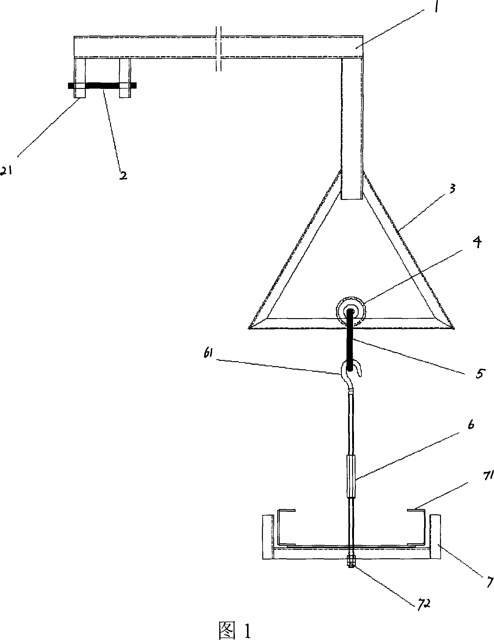
[0029] Such as figure 1 Shown: a long-span cable tray installation mold, which includes:

[0030] Right angle cantilever 1;

[0031] A bolt 2, the end of the horizontal side of the right-angled cantilever 1 is provided with a bolt bracket 21 oppositely arranged to support the bolt 2 horizontally;

[0032] A spreader sliding bracket 3, which is an isosceles triangle, its top is fixedly connected to the vertical edge of the right-angled cantilever 1, and its bottom edge has a U-shaped groove (not shown in the figure);

[0033] A bearing 4, which is arranged in the groove of the bottom edge of the said spreader sliding bracket 3 and can roll left and right; The clamping plate of above-mentioned bearing 4 (not shown in the figure);

[0034] A circular ring 5, which passes through the center of the bearing 4 and surrounds the bottom edge of the spreader sliding bracket 3;

[0035] A rigging turnbuckle 6, the top end of which includes a hook 61, and is hooked on the ring 5 by th...


PUM


Abstract

The invention relates to mounting of large span bridges, in particular to a mounting mould for a large span cable bridge, which comprises a right angle cantilever, a bolt, a hanger sliding support, a bearing, a ring, a rigging turnbuckle and a hanger bracket, wherein the bolt is horizontally connected to the end portion of a horizontal edge of the right angle cantilever, the top end of the hangersliding support is fixedly connected to a vertical edge of the right angle cantilever, the bearing is arranged in a groove of a bottom side of the hanger sliding support and can roll right and left, the ring penetrates through the bearing center and surrounds the bottom side of the hanger, and the top end of the rigging turnbuckle is hooked to the ring via a hook. The invention further provides amethod utilizing the mounting mould for large span cable bridges to mount cable bridges, which comprises steps of measuring and manufacturing the mounting mould for large span cable bridges on the site, fixing a bridge with the mounting mould, hoisting, adjusting the cable bridge and then fixing in position. The invention solves difficulties of low construction efficiency and high safety hazards during construction of high-altitude large span cable bridges, and further increases construction efficiency.

Description

technical field [0001] The invention relates to the installation of a bridge frame, in particular to the installation of a long-span bridge frame. Background technique [0002] Cable tray construction is an important part of electrical construction. The long-span bridge is a cable bridge with a length of 6-7 meters suitable for high altitudes. Due to the length, the side panels of the long-span bridge are made of double-layer galvanized sheets, and the weight (60-80kg / piece) is much larger than that of ordinary 2 The combined weight of the 3 sections of the meter bridge. Therefore, the construction of high-altitude long-span bridges generally requires the use of driving or truck cranes in the workshop. When installing a long-span bridge under the high-altitude platform, it is impossible to use the driving or truck crane in the factory building, and the construction can only be done on the scaffold by manpower. Due to the length and weight of the long-span bridge, the cons...

Claims


Application Information

Patent Timeline
Patent Type & Authority Patents(China)
IPC IPC(8): H02G1/00H02G3/30B66C1/10
Inventor 郭宏谢融沈玉坤金叙周捷
Owner CHINA MCC20 GRP CORP
Why Eureka
Try Eureka