Heat radiating fin and heat radiator

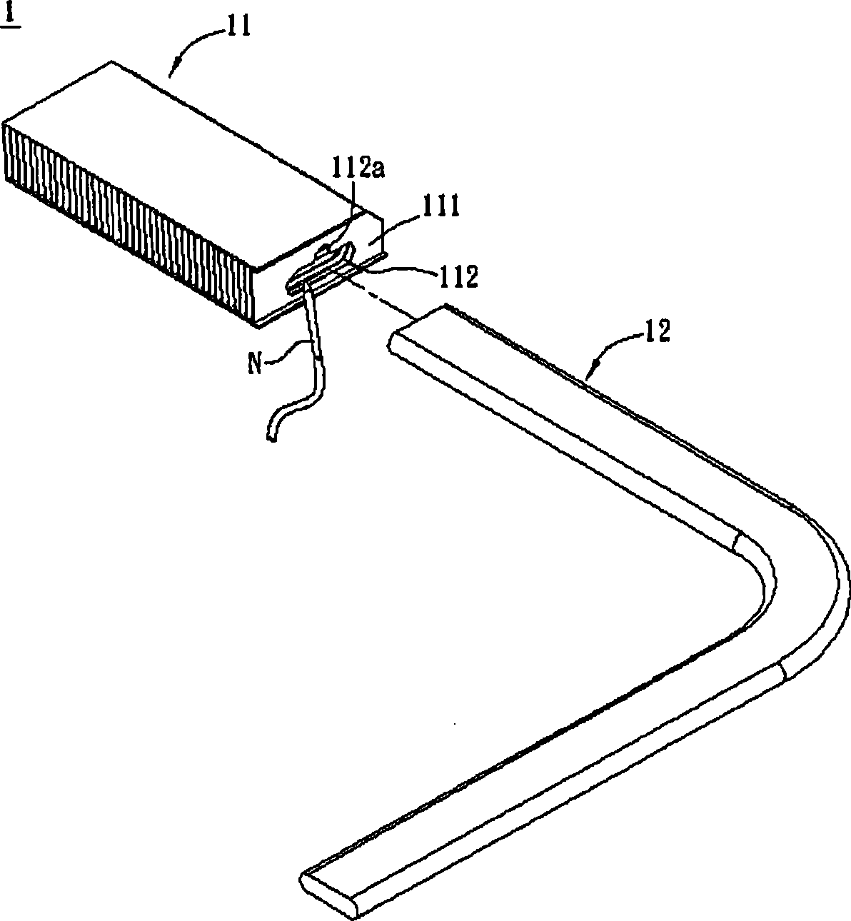
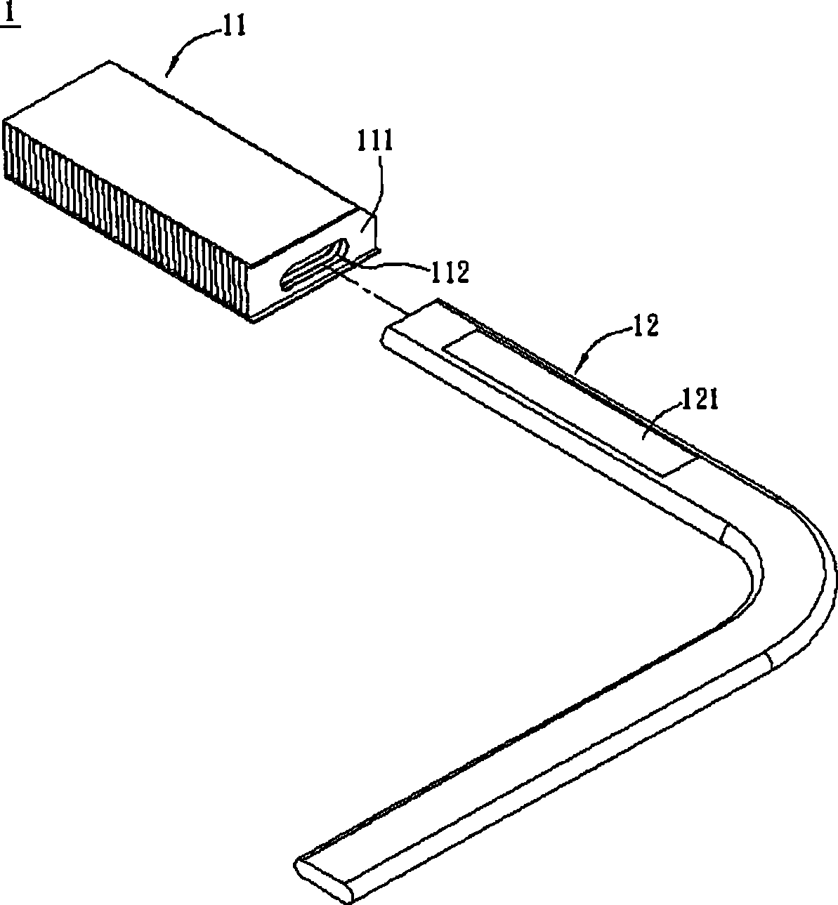
A heat sink and heat sink technology, which is applied in the direction of electric solid devices, semiconductor devices, cooling/ventilation/heating transformation, etc., can solve the problem that the combination of heat pipe 12 and heat sink group 11 is reduced, and the other end of the accommodating hole 112 Problems such as overflow, uneven thickness of solder paste, etc., to save costs, speed up the time of setting solder paste, and improve the uniformity of the effect

Inactive Publication Date: 2009-06-17
ASUSTEK COMPUTER INC
View PDF0 Cites 4 Cited by
  • Summary
  • Abstract
  • Description
  • Claims
  • Application Information

AI Technical Summary

Problems solved by technology

However, since there is no positioning mechanism, when the heat pipe 12 is placed into the accommodating hole 112, the solder paste 121 on the upper part of the heat pipe 12 will be scraped off by the wall of the accommodating hole 112, or squeezed out of the accommodating hole 112. If the other end overflows, it is necessary to manually wipe the overflowing solder paste
In this way, the thickness of the solder paste will still be uneven, resulting in a decrease in the bonding tightness between the heat pipe 12 and the heat sink group 11

Method used


Image

  • Heat radiating fin and heat radiator
  • Heat radiating fin and heat radiator
  • Heat radiating fin and heat radiator

Examples


Embodiment Construction

[0014] Hereinafter, a heat sink and a heat sink according to a preferred embodiment of the present invention will be described with reference to the related drawings, wherein the same components will be described with the same reference signs.

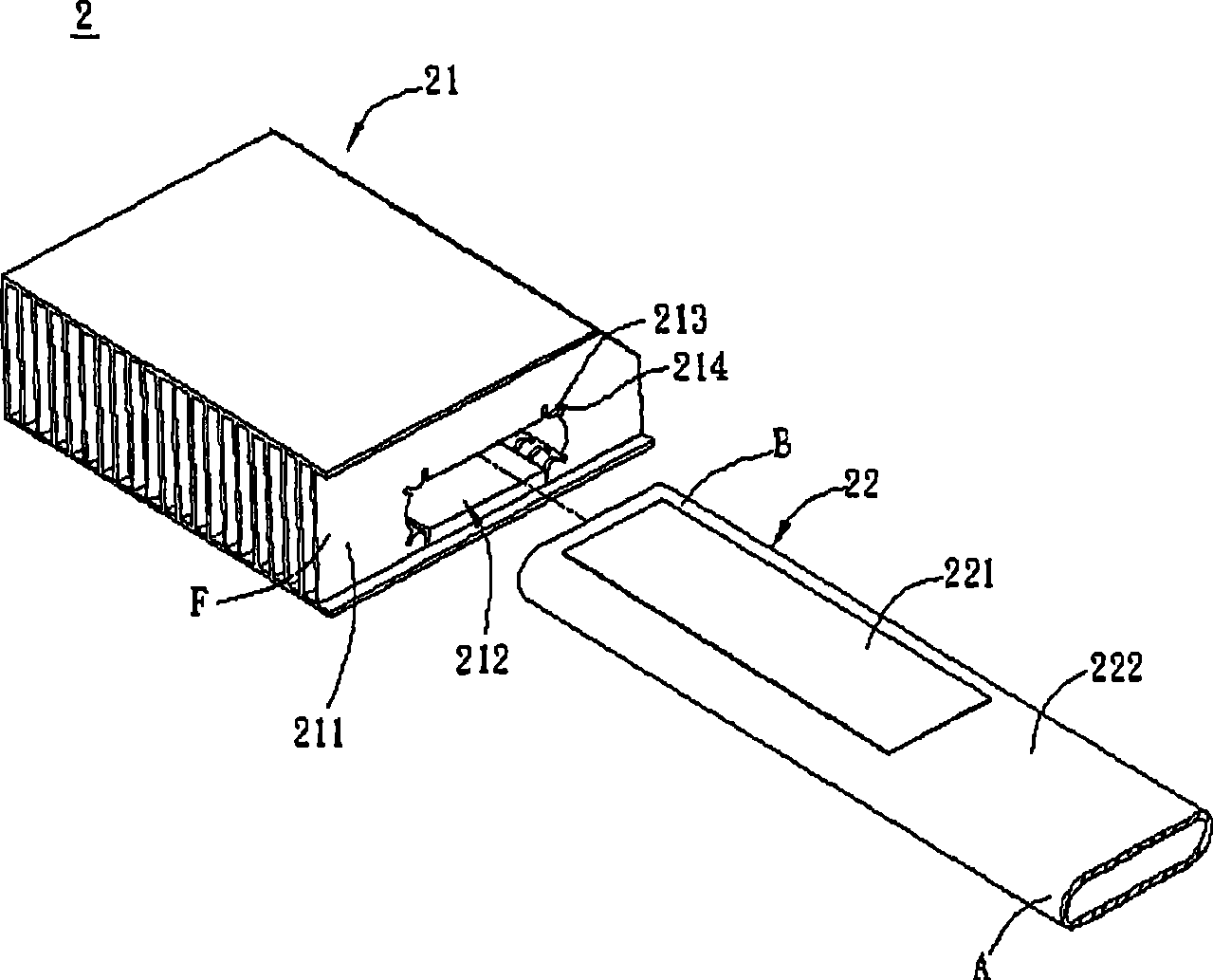
[0015] figure 2 Shown is a heat sink 2 according to a preferred embodiment of the present invention. The heat sink 2 includes a heat sink group 21 and a heat pipe 22 . image 3 Shown is a schematic cross-sectional view of the heat sink 211 with the heat pipe 22 passing through the accommodating hole 212 . Please refer to figure 2 and image 3 Explain radiator 2.

[0016] The heat sink set 21 has a plurality of heat sinks 211 connected to each other. Each heat sink 211 has a heat sink body F and a plurality of positioning protrusions 213. The heat sink body F has an accommodating hole 212 for the heat pipe 22 to pass through. The accommodating holes 212 of the heat sinks 211 are aligned with each other, and the positioning protrus...


PUM


Abstract

The invention relates to a radiating fin used for a heat pipe to thread, which comprises a radiating body and a plurality of positioning convex portion. The radiating body has a containing hole for the heat pipe to thread. The positioning convex portion is formed on the peripheral edge of the containing hole for supporting the heat pipe, which makes the heat pipe and the peripheral edge of the containing hole keep a gap.

Description

technical field [0001] The present invention relates to a heat-conducting element, in particular to a heat sink group and a heat sink. Background technique [0002] With the advancement of technology, the integration of electronic components is also continuously improved, so that more and more heat is generated during the operation of electronic devices. How to improve the heat dissipation performance to maintain the stability of the operation of the electronic device has become an important issue. Among them, a fin assembly and a heat pipe are common radiators. [0003] like Figure 1A As shown, a known heat sink 1 includes a heat sink set 11 and a heat pipe 12 . The heat sink set 11 is formed by connecting a plurality of heat sinks 111 to each other, and a accommodating hole 112 is formed to accommodate the heat pipe 12 . The relative positions of the heat sink group 11 and the heat pipe 12 can be fixed by means of solder paste. Among them, there are the following two ...

Claims


Application Information

Patent Timeline
Patent Type & Authority Applications(China)
IPC IPC(8): H05K7/20H01L23/24H01L23/40
Inventor 萧名扬
Owner ASUSTEK COMPUTER INC
Why Eureka
Try Eureka