Automatic irrigation system

An automatic irrigation system and solenoid valve technology, applied in horticulture, botany equipment and methods, cultivation, etc., can solve the problems of increasing the cost of use, low precision of instruments, and affecting plant growth, so as to increase the application possibility and reduce the The effect of manual operation and water saving

Inactive Publication Date: 2009-06-24
上海艾美克电子有限公司
View PDF0 Cites 26 Cited by
  • Summary
  • Abstract
  • Description
  • Claims
  • Application Information

AI Technical Summary

Problems solved by technology

The disadvantage of this system is that it is not possible to adjust the irrigation time according to the season and weather. Whether it is drought or sufficient rain, it will irrigate according to the set time and irrigation amount, which not only affects the growth of plants, but also causes great damage. of water waste
Not suitable for water-scarce areas
[0004] 2. Timely irrigation system: The irrigation system can control the irrigation system to irrigate according to the detected local soil moisture content. However, due to the great differences in the soil in various places and the low precision of the instrument, the detection results will be inconsistent. Larger errors, resulting in misfilling
If you use precision instruments imported from foreign countries,

Method used


Image

  • Automatic irrigation system
  • Automatic irrigation system
  • Automatic irrigation system

Examples


specific Embodiment 1

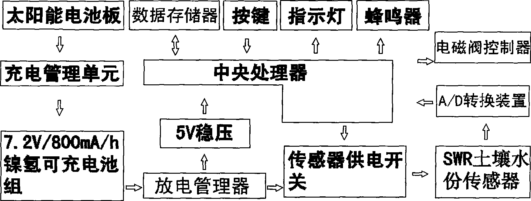
[0035] figure 1 The principle of the wired automatic irrigation system of the present invention is given. The system is mainly composed of a main control device, a solenoid valve, and a sensor device. , indicator light and buzzer. The solenoid valve in this system uses a self-holding solenoid valve, which is controlled by the central processing unit in the main control device. The conversion device and the sensor power supply switch are connected to the central processing unit. The power supply device in the device is composed of a solar panel, a charge manager, a Ni-MH rechargeable battery pack and a discharge manager connected in sequence, and the discharge manager is respectively connected to the central processing unit and the sensor power supply switch. The above-mentioned data memory connected with the central processing unit is adopted as EEPROM.

[0036] When the system is running, the power supply of the whole device is powered by a 7.2V / 800mA / h Ni-MH rechargeable ...

specific Embodiment 2

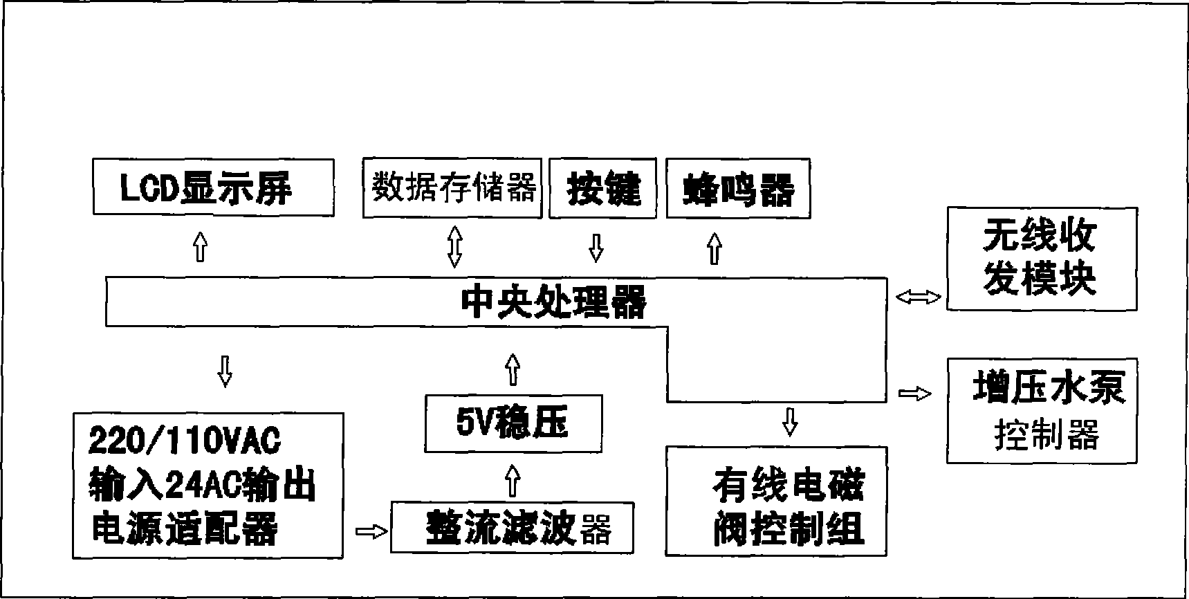
[0039] In this example, the Figure 3 to Figure 5 The principle shown, image 3 The principle structure of the group control device in this system is given. Its internal central processing unit is respectively connected to the LCD display, data memory, buttons, buzzer, power adapter and rectifier filter in the power module. At the same time, the central processing unit The transmitter is also connected with a wireless transceiver, a wired solenoid valve control group and a booster water pump control device.

[0040] Figure 4 The principle block diagram of the wireless solenoid valve device is given, which includes the central processing unit and the power supply unit connected to it, data memory EEPROM, indicator light, wireless transceiver and solenoid valve. The solenoid valve is a pulse-triggered self-holding solenoid valve. At the same time, the solar battery panel, the charge manager, the rechargeable battery pack and the discharge manager in the power supply device a...


PUM


Abstract

The invention discloses an automatic irrigation system, comprising a main control device, an electromagnetically operated valve and a sensing device, wherein the main control device controls the electromagnetically operated valve and the sensing device through two modes of a radio way and a wired way. The inventive wired automatic irrigation system can be applied for irrigation of small area e.g. a garden, and the radio group control automatic irrigation system can be applied for irrigation of large area e.g. the field, thereby greatly reducing manual manipulation, which is of manual manipulation and greatly saves water source.

Description

technical field [0001] The invention relates to an automatic control system, in particular to an automatic irrigation system applied in agriculture or gardening. Background technique [0002] The planting of plants needs to keep a certain humidity and moisture in the soil in which it is planted, which requires people to water the plants frequently. The amount of watering to plants is affected by time and geographical location. If the plants are not properly irrigated in time, the growth of the plants will be adversely affected, and even the plants will wither due to lack of water. For example, if the family plants flowers, if the flowers cannot be watered in time to replenish water, the flowering period or the overall appearance of the flowers will be affected, and the growth of the flowers will also be affected if the water is too much. At present, the main irrigation systems in my country mainly include the following types: [0003] 1. Timing irrigation system: Most of t...

Claims


Application Information

Patent Timeline
IPC IPC(8): A01G25/16G05B19/02
Inventor 柯智勇
Owner 上海艾美克电子有限公司
Why Eureka
Try Eureka