Aspheric surface detecting instrument

An aspheric surface and detector technology, applied in instruments, measuring devices, optical devices, etc., can solve the problems of low detection accuracy and efficiency of optical aspheric surfaces, and achieve the effect of improving measurement accuracy

Inactive Publication Date: 2009-06-24
XIAMEN UNIV
View PDF0 Cites 9 Cited by
  • Summary
  • Abstract
  • Description
  • Claims
  • Application Information

AI Technical Summary

Problems solved by technology

[0007] The purpose of the present invention is to solve the problems of low detection accuracy and efficiency of the existing optical aspheric surface, and provide a combination of the advantages and disadvantages of non-contact and contact measurement, and integrate the contact and non-contact measurement together to measure the aspheric surface. Perform measurement and compensate each other through two methods to obtain an aspheric surface detector with higher measurement accuracy

Method used


Image

  • Aspheric surface detecting instrument
  • Aspheric surface detecting instrument
  • Aspheric surface detecting instrument

Examples


Embodiment Construction

[0020] The embodiments of the present invention will be further described below in conjunction with the accompanying drawings.

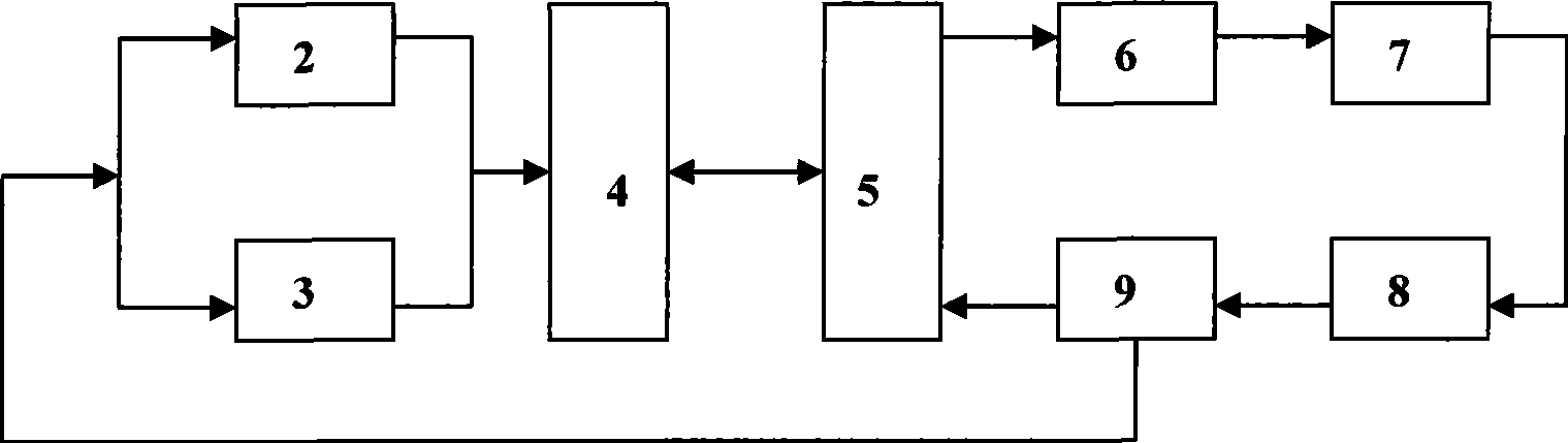
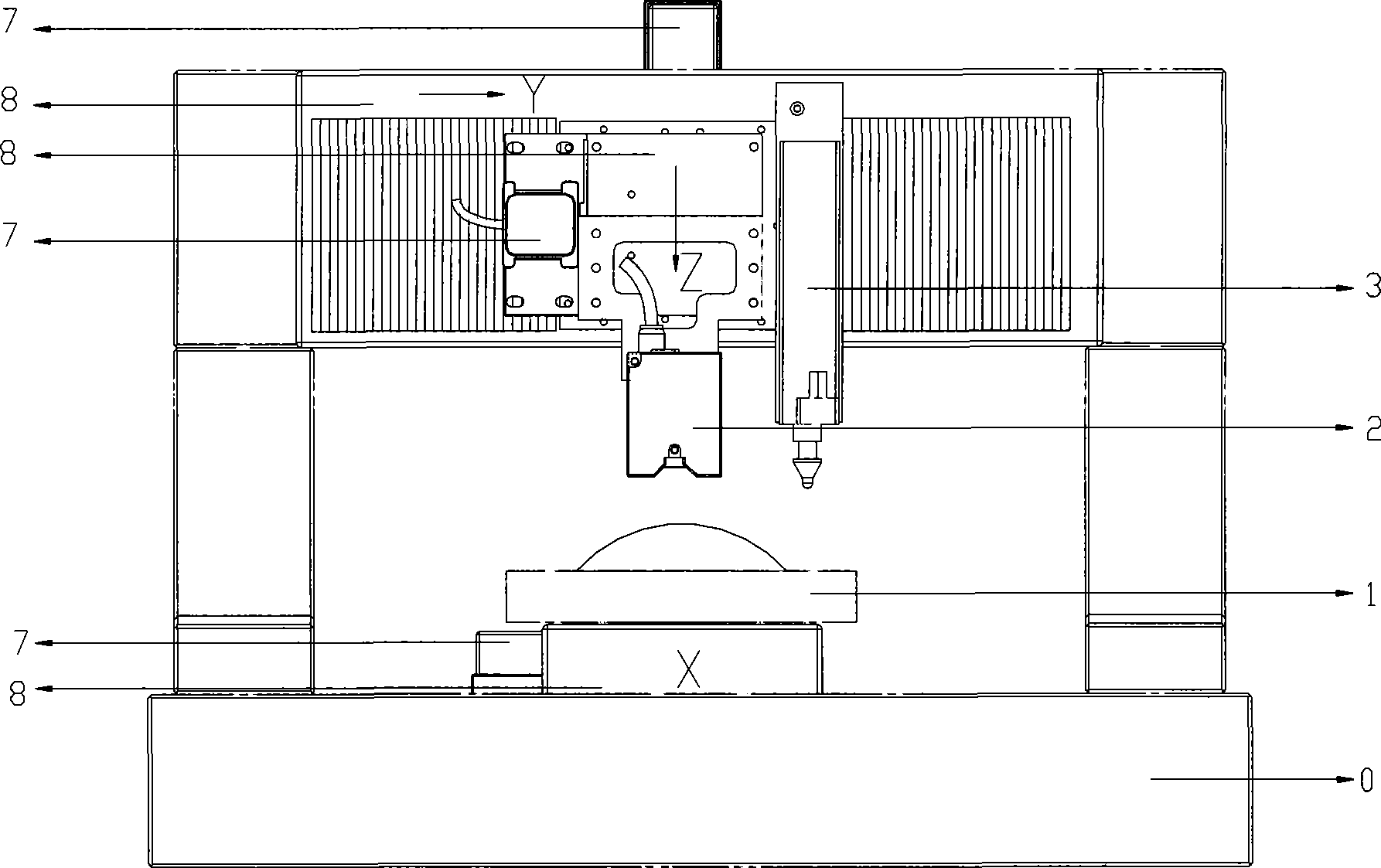
[0021] see figure 1 with 2 , the present invention is equipped with a granite structure frame 0, a granite ultra-precision detection platform 1, an automatic focusing non-contact laser displacement measuring head 2, a grating contact displacement measuring head 3, a computer 4, a four-axis motion control card 5, a driver 6, and a press Electric ceramic motor 7, XYZ axis motion mechanism 8 and grating ruler 9.

[0022] The XYZ three-axis movement mechanism 8 is installed and fixed on the granite structure frame 0, the automatic focusing non-contact laser displacement measuring head 2 and the grating contact displacement measuring head 3 are respectively installed and fixed on the Z-axis movement mechanism, and the granite ultra-precision detection platform 1 is set On the X-axis motion mechanism; the XYZ three-axis motion mechanism 8 is equipped wit...


PUM


Abstract

The invention relates to optical aspheric detecting devices, and provides an aspheric detector, particularly an aspheric detector with higher measuring accuracy, which is obtained by combining the advantages and disadvantages of contact and non-contact measurement, integrating the contact and non-contact measurement as a whole to measure aspheric surfaces and mutually compensating for the two methods of measurement. The aspheric detector comprises a structure rack, a detecting platform, a non-contact laser displacement probe, a grating contact displacement probe, an XYZ three-axis motion mechanism and a control device, wherein, the non-contact laser displacement probe and the grating contact displacement probe are mounted on the Z axis of the XYZ three-axis motion mechanism; the detecting platform is arranged on the X axis motion mechanism; an X-axis motor, a Y-axis motor and a Z-axis motor are mounted on the XYZ three-axis motion mechanism respectively; and the XYZ three-axis motion mechanism is driven by the X axis motor, the Y axis motor and the Z axis motor, thereby realizing the movement of the non-contact laser displacement probe and the grating contact displacement probe, and realizing the three-dimensional measurement of an aspheric surface optical element.

Description

technical field [0001] The invention relates to an optical aspheric surface detection device, in particular to a combined contact and non-contact aspheric surface detection instrument. Background technique [0002] Compared with spherical optical elements, aspheric surfaces have many advantages in optical design. When used in optical systems, spherical aberration, coma, astigmatism, and field curvature can be eliminated, light energy loss can be reduced, and high imaging quality can be obtained. At the same time, it can reduce optical system reduce the volume of the optical system (see literature: Machkour-Deshayes N, Stoup J, Lu ZQJ, et al. Form-profiling of optics using the geometry measuring machine and the M-48 CMM at NIST. JOURNAL OFRESEARCH OF THE NATIONAL INSTITUTE OF STANDARDS AND TECHNOLOGY 111(5): 373-384 SEP-OCT 2006). It can be widely used in modern optoelectronic products and image processing products, as well as military, astronomical and other fields. Howeve...

Claims


Application Information

Patent Timeline
Patent Type & Authority Applications(China)
IPC IPC(8): G01B11/24
Inventor 郭隐彪刘建春刘古今朱永炉
Owner XIAMEN UNIV
Why Eureka
Try Eureka