Interconnection line test circuit used in field programmable gate array device

A technology for testing circuits and interconnecting wires, applied in the direction of measuring electricity, measuring electrical variables, and electronic circuit testing, etc., can solve problems such as inapplicability, and achieve the effects of improving reliability, reducing configuration, and shortening test time

CN101464494AInactive Publication Date: 2009-06-24无锡引速得科技有限公司
0 Cites 14 Cited by

Patent Information

Authority / Receiving Office
CN · China
Current Assignee / Owner
Publication Date
2009-06-24
Estimated Expiration
Not applicable · inactive patent

Smart Images

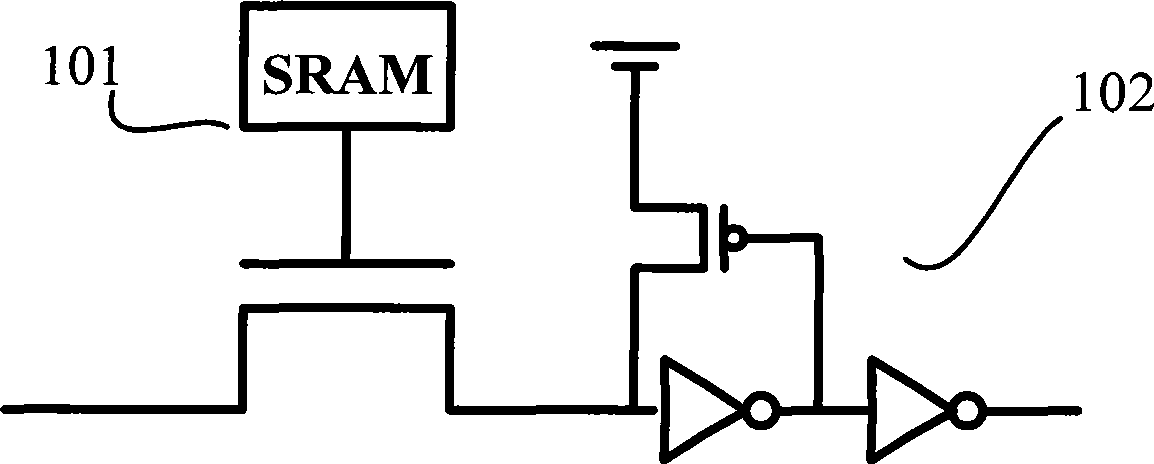
  • Figure 1
    Figure 1
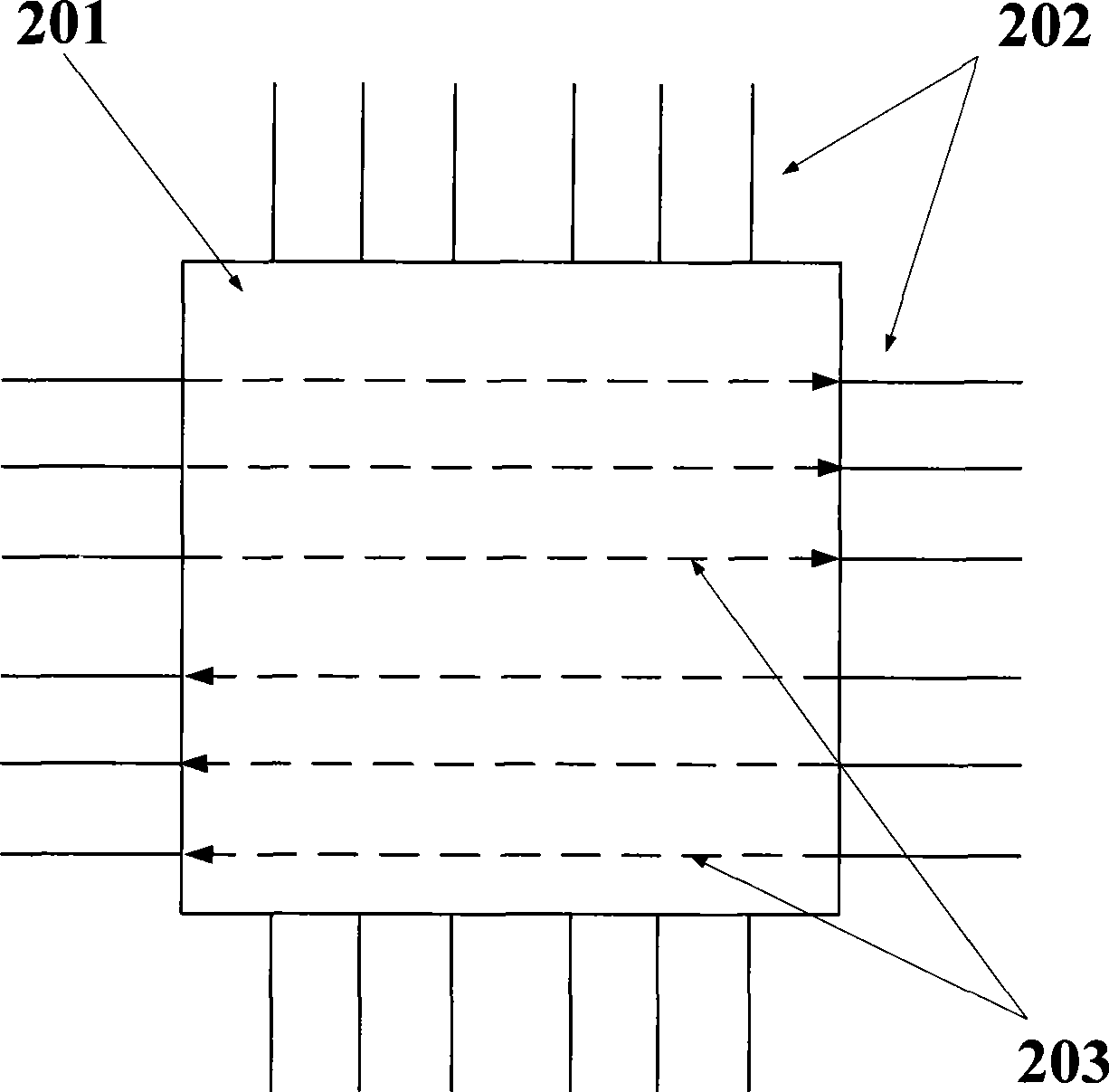
  • Figure 2
    Figure 2
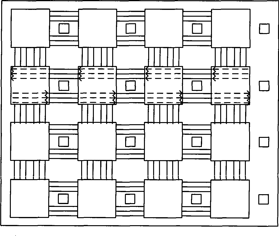
  • Figure 3
    Figure 3
Patent Text Reader

Abstract

The invention relates to an interconnection line testing circuit used in a field programmable gate array device, which comprises even number of vector generation and respond analyzers. Each vector generation and respond analyzer in the even number of vector generation and respond analyzers comprises an n-input and n-output logic combined circuit and a group of n-bit registers, wherein, n is a natural number; and every two vector generation and respond analyzers are connected by interconnection lines with opposite direction and the bit width of n and are combined into a built-in self-testing circuit. The built-in self-testing circuit can achieve the simultaneous test of the two groups of interconnection lines with opposite direction and larger bit width on the condition that the number of the registers is not changed, shorten the testing time of a FPGA device, and reduce the testing cost of the FPGA device.
Need to check novelty before this filing date? Find Prior Art

Description

technical field

[0001] The invention relates to an interconnection testing technology, in particular to an interconnection circuit used in a field programmable gate array device. Background technique

[0002] Field Programmable Gate Array (Field Programmable Gate Array, FPGA) is composed of logic cell array (Logic Cell Array, LCA), which includes configurable logic block (Configurable Logic Block, CLB), output and input module (InputOutput Block, IOB) and internal wiring (Interconnect, IR) three parts; IOB can provide the connection interface between FPGA internal logic and package pins, CLB can be used to realize the logic and timing storage function of FPGA chip, and IR is used to realize FPGA Signal communication between CLB and IOB in the chip.

[0003] There are configurable logic and timing resources such as look-up tables (Look Up Table, LUT) and registers in the two-dimensional CLB array to realize logic design and timing design functions; in FPGA, each CLB correspo...

Examples

Embodiment Construction

[0037] In order to make the above objects, features and advantages of the present invention more comprehensible, the present invention will be further described in detail below in conjunction with the accompanying drawings and specific embodiments.

[0038] FPGA devices have the advantages of high integration, small size, special application functions can be realized through user programming, short design and development cycle, reconfigurability, etc., and then become a hot spot in the development of electronic systems.

[0039] In the basic structure of FPGA, CLB is the basic unit for realizing user functions. Multiple logic function blocks are usually arranged in an array structure regularly and distributed throughout the FPGA chip; IOB completes the interface between the internal logic of FPGA chip and external pins, and surrounds Around the logic cell array; IR includes wiring segments of various lengths and some programmable connection switches, which connect each CLB or I...