Supercharge Your Innovation With Domain-Expert AI Agents!

LCD device

A liquid crystal display and liquid crystal panel technology, applied in the direction of instruments, lighting devices, optics, etc., can solve the problems of light-emitting diode light-emitting function, lifespan, quality reduction, increased manufacturing cost, and the distance between the light-emitting surface and the display panel is shortened, so as to avoid Headlight effect, lower production cost, perfect mixed light effect

Inactive Publication Date: 2009-06-24
CHUNGHWA PICTURE TUBES LTD
View PDF0 Cites 5 Cited by
  • Summary
  • Abstract
  • Description
  • Claims
  • Application Information

AI Technical Summary

Problems solved by technology

However, the heat dissipation path through the carrier substrate 12 and the plastic frame 13 is long, and the light emitting diodes 11 of the light bar 15 are likely to suffer from poor heat dissipation.
[0004] To sum up, if the light emitting diodes 11 are first fixed on the carrier substrate 12 to form the light bar 15 in the prior art, the manufacturing cost will be increased because the carrier substrate 12 is needed; in addition, because the thickness of the carrier substrate 12 is relatively Thick, so that the distance between the light-emitting surface of the light-emitting diode 11 and the display panel is shortened, and the ratio (A / P ratio) of "the distance P between the light-emitting diodes 11" and "the distance A between the light-emitting diode and the display panel" is smaller Therefore, if the design or device is not good, it may cause the headlight effect, or the light mixing distance is reduced, so that the light mixing effect is not perfect; The heat dissipation effect of the light-emitting diode is greatly reduced, so the light-emitting function, life and quality of the light-emitting diode will be reduced

Method used


Image

  • LCD device
  • LCD device
  • LCD device

Examples


Embodiment Construction

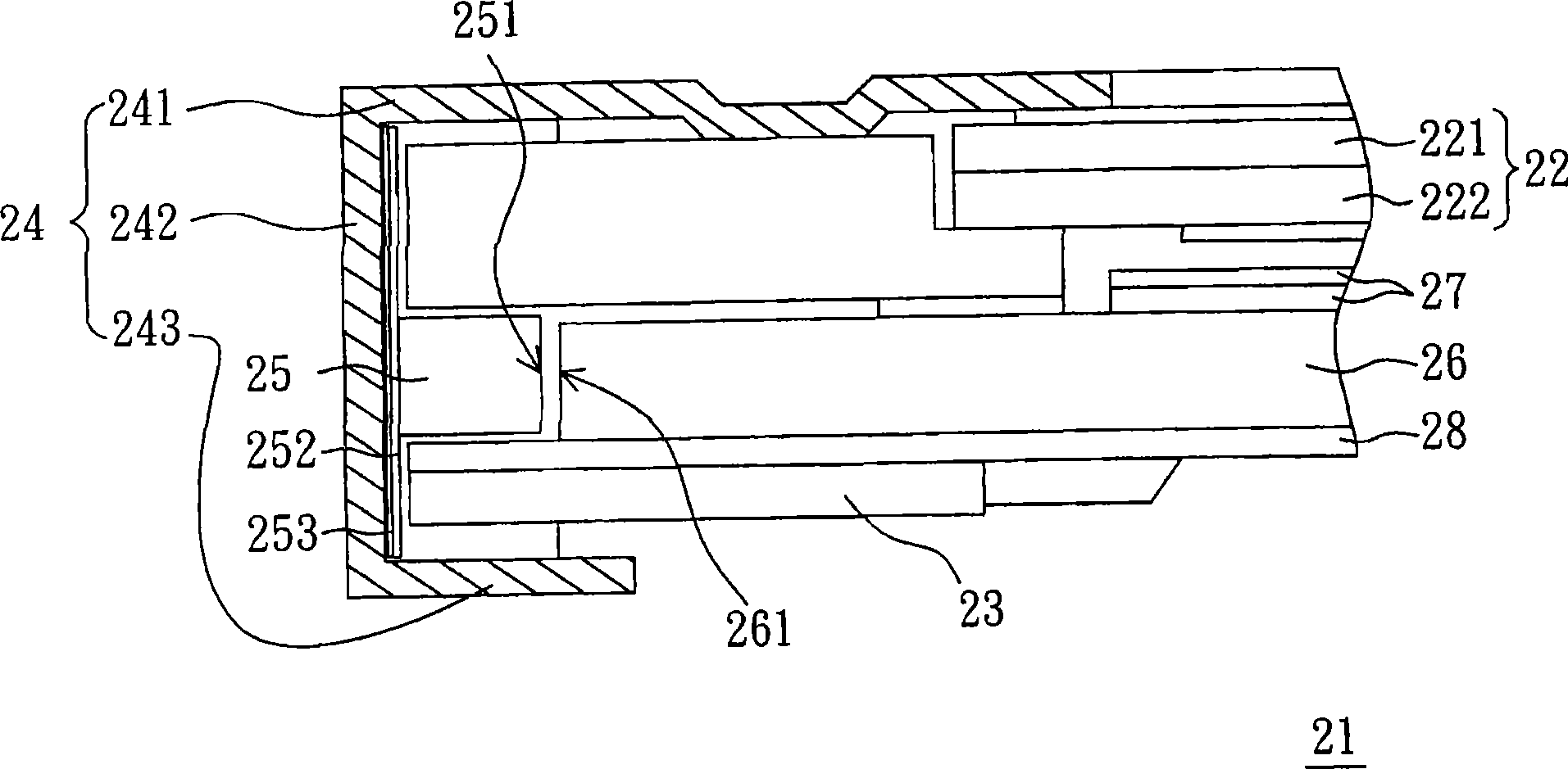
[0021] Please refer to figure 2 , figure 2 It is a cross-sectional view of the structure of a liquid crystal display according to an embodiment of the present invention. Depend on figure 2 It can be seen that the liquid crystal display 21 of this embodiment mainly includes a first frame 23 , a light guide plate 26 , a second frame 24 , a plurality of LEDs 25 and a liquid crystal panel 22 . The light guide plate 26 is disposed on the first frame 23 , and the light guide plate 26 has a light incident surface 261 . The second frame 24 is disposed above the light guide plate 26 . The light emitting diodes 25 are disposed inside the second frame 24 and adjacent to the light incident surface 261 of the light guide plate 26 . Wherein, the light emitting diode 25 can be a surface mount type light emitting diode component.

[0022] Based on the above, the liquid crystal panel 22 is mainly used for displaying images, located in the accommodating space of the second frame 24 and ...


PUM


Abstract

The invention relates to a liquid crystal display including a first framework, a light guide plate, a second framework, a light emitting diode and a liquid crystal panel. The light guide plate is arranged on the first framework and provided with a light incidence surface. The second framework covers the upper part of the partial light guide plate. The light emitting diode is arranged on the inner side of the second framework and abuts on the light incidence surface of the light guide plate. The liquid crystal panel is arranged between the second framework and the light guide plate.

Description

technical field [0001] The invention relates to a liquid crystal display, in particular to a liquid crystal display whose light source is a light emitting diode. Background technique [0002] At present, light emitting diodes (LEDs) are used as light sources for displays, and most of them use light bar manufacturing methods. Some components of the backlight module such as the light guide plate are combined to form the light source of the backlight module. [0003] Please refer to the schematic diagram of the structure of the existing liquid crystal display figure 1 . Generally, in the liquid crystal display 10 , the light source is a light bar 15 . The light bar 15 is formed by combining the light emitting diodes 11 and the carrier substrate 12 , and the light bar 15 is fixed on the plastic frame 13 . Therefore, to make figure 1 For the liquid crystal display 10 , the LED 11 and the carrier substrate 12 must first be combined to form the light bar 15 . Since the light ...

Claims


Application Information

Patent Timeline
IPC IPC(8): G02F1/13357F21V23/06H05B37/02
Inventor 叶格铭杨瑞雄谢襦毅
Owner CHUNGHWA PICTURE TUBES LTD
Features
  • R&D
  • Intellectual Property
  • Life Sciences
  • Materials
  • Tech Scout
  • Unparalleled Data Quality
  • Higher Quality Content
  • 60% Fewer Hallucinations
Learn More