
Drive method and drive device capable of regulating high-power LED lighteness

A driving method and a technology of a driving device, which are applied in the direction of lighting devices, lamp circuit layout, light sources, etc., can solve problems such as difficulty in increasing the refresh rate of gray levels, limiting the maximum frequency of PWM signals, and deteriorating devices or equipment, etc., to achieve improvement Electromagnetic compatibility performance, increase the refresh rate of grayscale, and prolong the effect of working life

Inactive Publication Date: 2009-06-24
张家瑞 +1
View PDF0 Cites 36 Cited by
  • Summary
  • Abstract
  • Description
  • Claims
  • Application Information

AI Technical Summary

Problems solved by technology

But for high-power LEDs, due to the large driving current (usually hundreds of mA) and high driving voltage (when multiple high-power LEDs are driven in series, the driving voltage often reaches tens of volts), this greatly limits the PWM The highest frequency that the signal can reach, so the dimming effect of high-power LED dimming by PWM method is not very ideal, mainly in the two aspects that the gray level and gray refresh frequency are difficult to improve
In addition, the PWM method leads to the rapid on-off of the LED drive circuit current. In the case of high current and high voltage, it will form strong electromagnetic radiation to the surrounding environment and deteriorate the EMC (Electromagnetic Compatibility; electromagnetic compatibility) performance of the device or equipment.
PWM causes the current flowing through the LED to fluctuate drastically from 0 to hundreds of milliamps in a very short time, which will also affect the working life of the LED

Method used


Image

  • Drive method and drive device capable of regulating high-power LED lighteness
  • Drive method and drive device capable of regulating high-power LED lighteness
  • Drive method and drive device capable of regulating high-power LED lighteness

Examples


Embodiment Construction

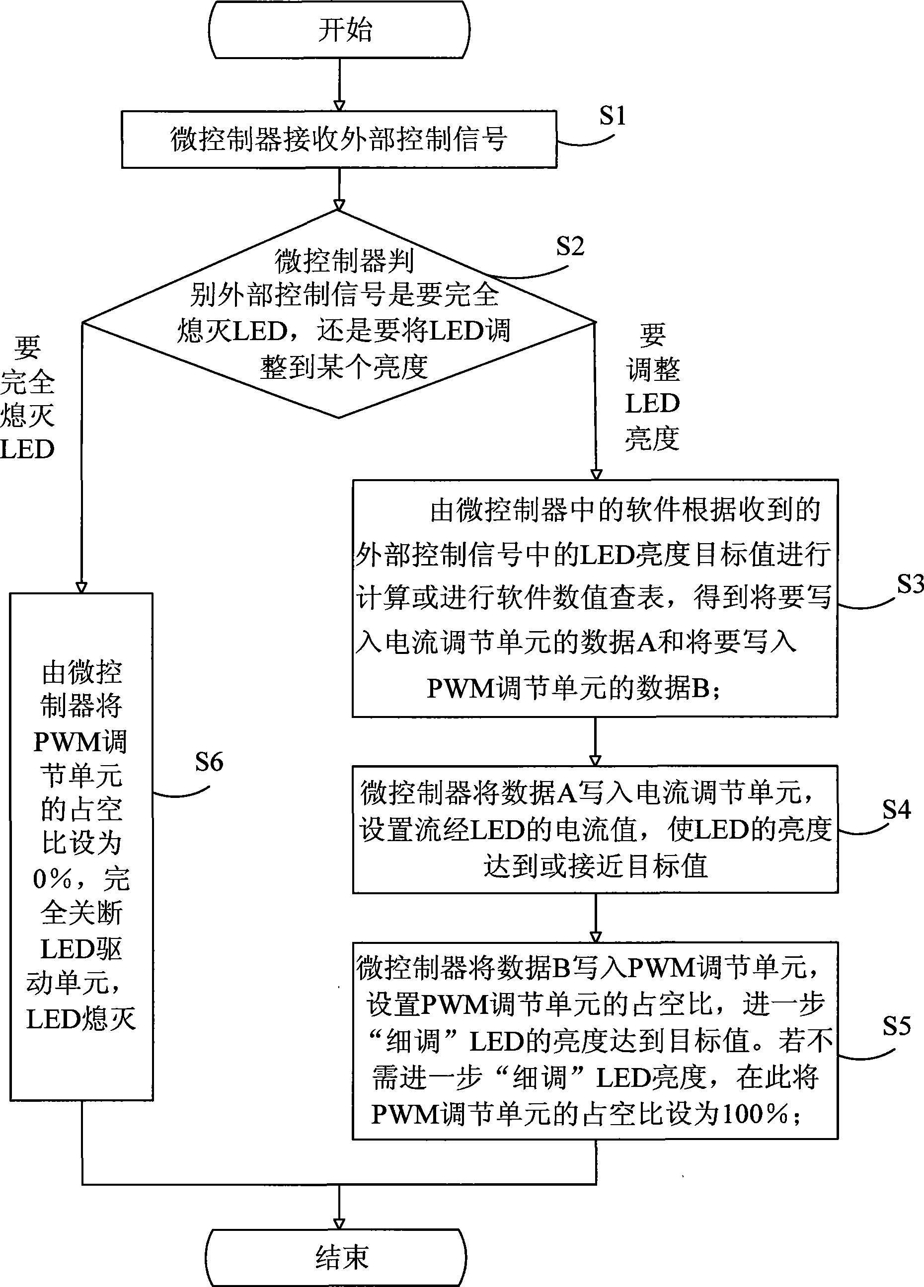
[0024] refer to figure 1 , the driving method capable of adjusting the brightness of high-power LED provided by the present invention comprises the following steps:

[0025] In step S1: the microcontroller receives an external control signal;

[0026] In step S2: the microcontroller judges the received control signal. Determine whether the external control signal is to completely turn off the LED or adjust the LED to a certain brightness, if it is necessary to completely turn off the LED, then perform step S6, and if it is necessary to adjust the LED to a certain brightness value, then perform step S3;

[0027] In step S6: the microcontroller sets the duty cycle of the PWM adjustment unit to 0%, completely turns off the LED drive unit, and the LED goes out, and completes a brightness adjustment process;

[0028] In step S3: the software in the microcontroller calculates according to the LED brightness target value in the received external control signal or performs a softwar...


PUM


Abstract

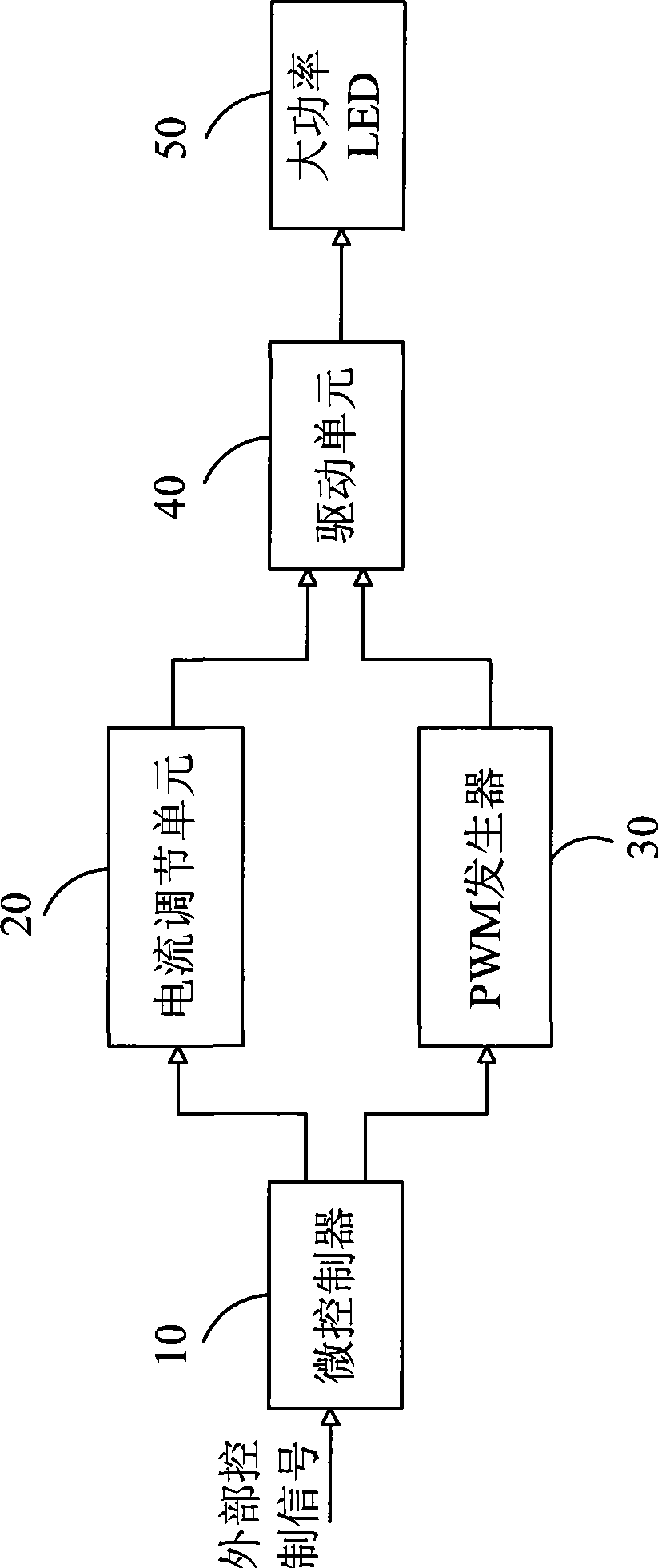
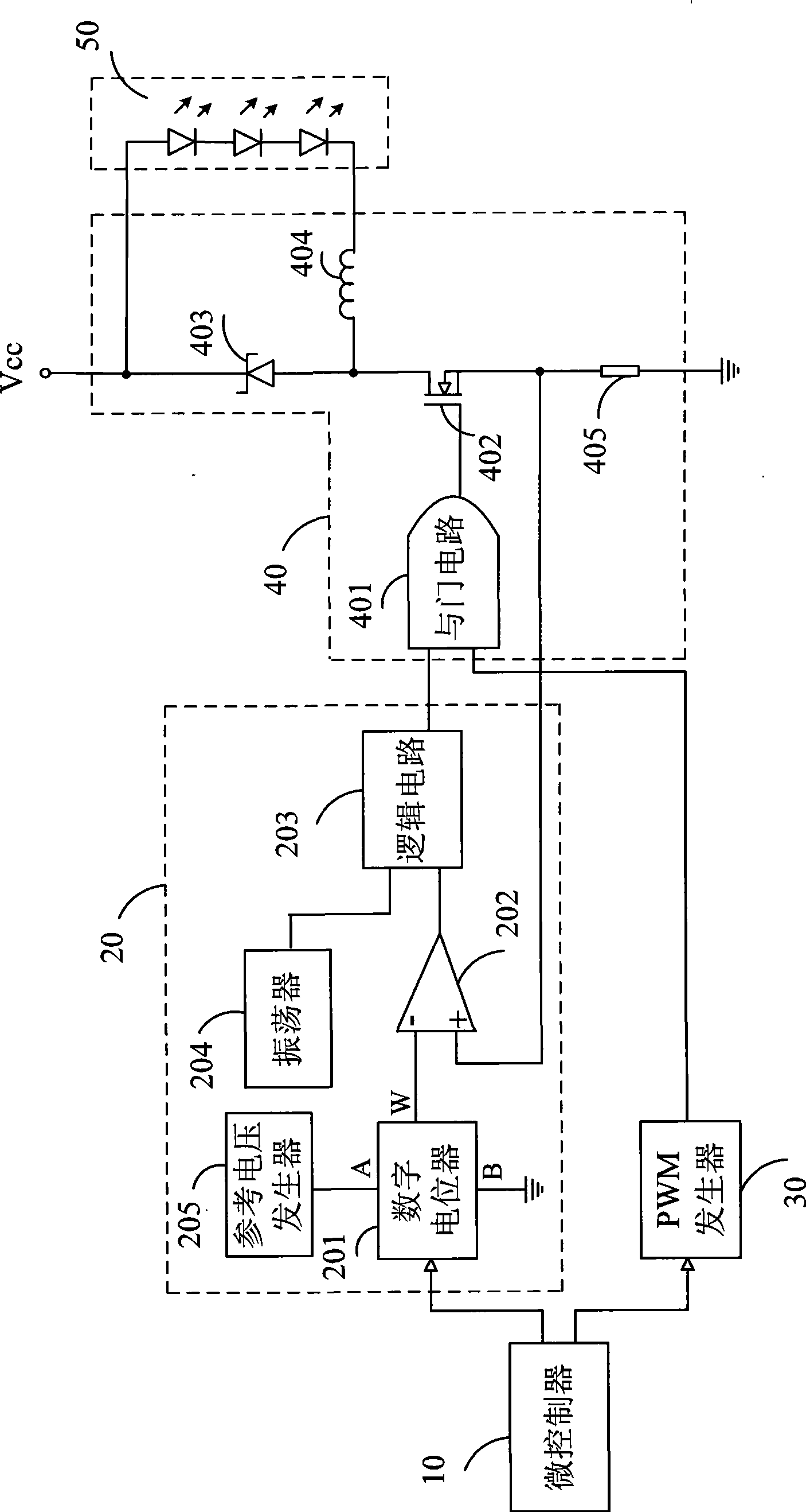
The invention provides a driving method and a device for adjusting LBD brightness with high power; the method can obtain the LBD brightness data through receiving the control information input from the outer side; the current flowing through the LBD can be set through a current adjusting unit connected with the driving unit, the LBD is lighted so as to lead the brightness to reach the target value; or the current flowing through the LBD can be set according to the method, the LBD brightness can be primarily adjusted, and then the signal dutyfactor of the PWM adjusting unit connected with the current adjusting unit in parallel is set, the LBD brightness is further adjusted to finally reach the target value; the LBD can be turned off through setting the dutyfactor of PWM adjusting unit signal to 0%. the technical proposal provided by the invention is utilized to dynamically adjust the LBD brightness in real time, and remarkably improve the EMC (electromagnetic compatibility) property of the device at the same time, and prolong the service life of the LED.

Description

technical field [0001] The invention relates to a high-power LED, in particular to a driving method and a driving device capable of adjusting the brightness of the high-power LED. Background technique [0002] In the prior art, PWM is usually used to adjust the brightness of LEDs. For low-power LEDs, the PWM dimming method is feasible because the driving current is not large and the driving voltage is not high. But for high-power LEDs, due to the large driving current (usually hundreds of milliamps), the high driving voltage (when multiple high-power LEDs are driven in series, the driving voltage often reaches tens of volts), which greatly limits the power of PWM. The highest frequency that the signal can reach, so the dimming effect of high-power LED dimming by PWM method is not very ideal, mainly in the two aspects that the gray level and gray refresh frequency are difficult to improve. In addition, the PWM method leads to the rapid on-off of the LED drive circuit current...

Claims


Application Information

Patent Timeline
IPC IPC(8): H05B37/02
Inventor 韦自力张家瑞
Owner 张家瑞
Learn More