LED drive circuit for PFM/PWM bimodal switch light modulation

A LED driving, dual-mode technology, applied in the field of microelectronics and solid-state electronics, can solve the problem of low efficiency, achieve the effect of simple overall structure, improve overall efficiency, and reduce complexity

Inactive Publication Date: 2009-06-24
XIAN JIEHANG ELECTRONICS SCI & TECH CO LTD
View PDF0 Cites 37 Cited by
  • Summary
  • Abstract
  • Description
  • Claims
  • Application Information

AI Technical Summary

Problems solved by technology

[0003] The purpose of the present invention is to provide a PFM / PWM dual-mode switching dimming LED drive circuit, which not only has higher conversion efficiency in the high brightness range, but also improves the duty cycle of the dimming mode in the low brightness range, and then Improve the efficiency of the entire LED drive circuit, and solve the problem of low efficiency in the low brightness range when the PWM mode is simply used for brightness adjustment in the existing LED drive circuit

Method used


Image

  • LED drive circuit for PFM/PWM bimodal switch light modulation
  • LED drive circuit for PFM/PWM bimodal switch light modulation

Examples


Embodiment Construction

[0019] The present invention will be described in detail below in conjunction with the accompanying drawings and specific embodiments.

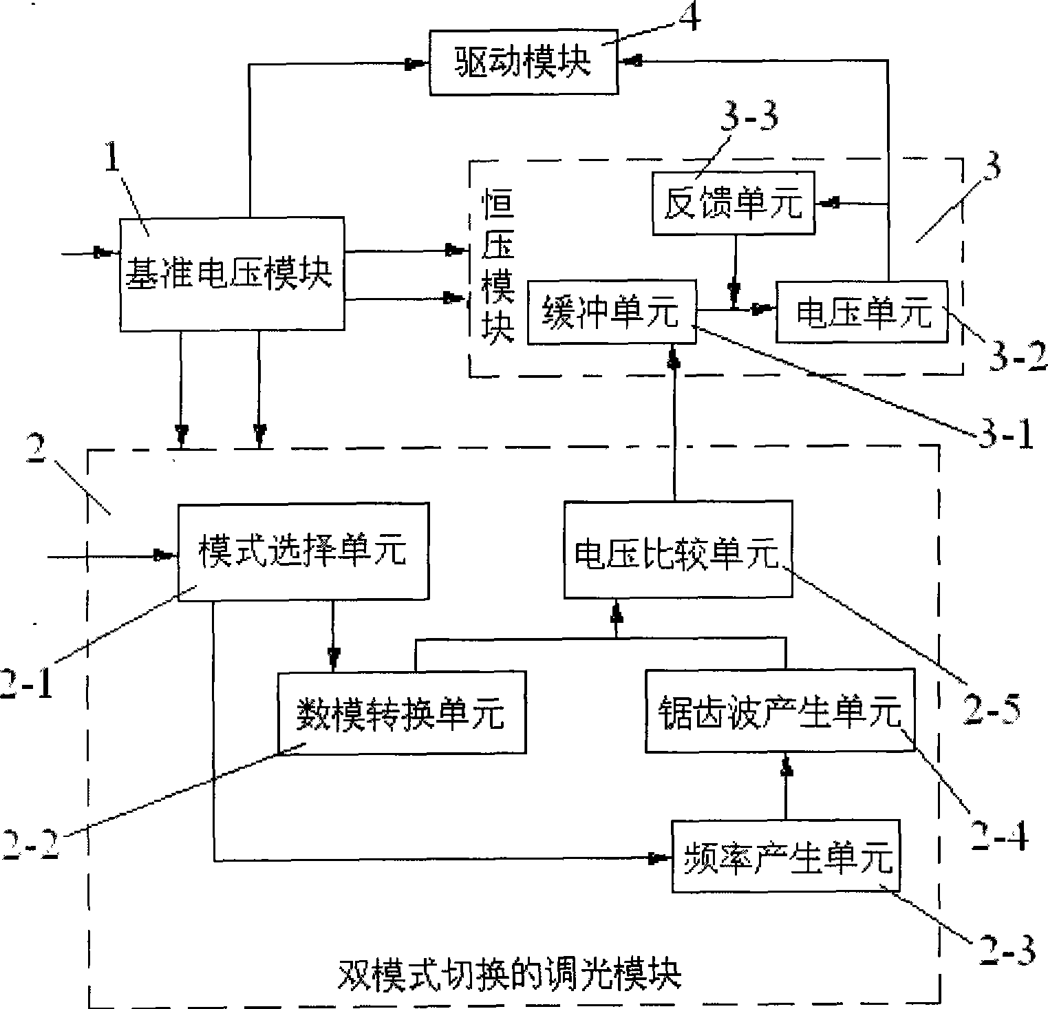
[0020] The structure of LED driving circuit of the present invention, as figure 1 shown. It includes a reference voltage module 1 and a dual-mode switching dimming module 2 , a constant voltage module 3 and a driving module 4 respectively connected thereto. The dimming module 2 with dual-mode switching includes a mode selection unit 2-1, a digital-to-analog conversion unit 2-2, a frequency generation unit 2-3, a sawtooth wave generation unit 2-4, and a voltage comparison unit 2-5, and the mode selection unit 2 -1 is connected with the digital-to-analog conversion unit 2-2 and the frequency generation unit 2-3 respectively, the frequency generation unit 2-3 is connected with the sawtooth wave generation unit 2-4, and the digital-to-analog conversion unit 2-2 and the sawtooth wave generation unit 2-4 are respectively connected with voltage co...


PUM


Abstract

The invention discloses a PFM / PWM dual-mode switching light-adjusting LBD driving circuit, which comprises a voltage reference module, and a dual-mode switching light-adjusting module, a constant voltage module and a driving module which are respectively connected with the voltage reference module; the voltage reference module is used for supplying power for each module and generating the voltage references in each module; the dual-mode switching light-adjusting module is used for generating the adjustable or the dutyfactor-adjusting square signals to control the constant voltage module according to the outer signal variation; the constant voltage module is used for generating the voltage to control the driving force of the driving module, and utilizing the internal feedback structure to ensure the stability of the voltage value; and the driving module is used for generating the constant driving current with the big enough peak value to satisfy the LBD lightening. The LBD driving circuit can supply the brightness adjusting function the same as the PWM light adjusting, and can switch to the PFM pattern under the low brightness condition at the same time, so as to effectively improve the whole efficiency of the driving circuit.

Description

technical field [0001] The invention belongs to the technical field of microelectronics and solid state electronics, and relates to an LED drive circuit, in particular to an LED drive circuit with PFM / PWM dual-mode switching and dimming. Background technique [0002] LED is the development trend of the lighting industry. It has the advantages of energy saving, environmental protection and long service life. It is one of the most promising high-tech fields in the 21st century. In the process of practical promotion of high-power white LEDs, how to make the driving circuit, one of the key technologies of LEDs, high-efficiency has become an urgent research content for the lighting industry. Currently used white LED drive circuits mostly use the PWM dimming mode. When the required brightness is large, the PWM dimming mode has a high conversion efficiency; when the required brightness is small, the duty cycle of the PWM dimming mode is very small. Low, greatly reducing the effici...

Claims


Application Information

Patent Timeline
Patent Type & Authority Applications(China)
IPC IPC(8): H05B37/02
Inventor 杨媛宋征华高勇
Owner XIAN JIEHANG ELECTRONICS SCI & TECH CO LTD
Why Eureka
Try Eureka