
Thermal expansion machine for producing stainless steel tube

A technology for stainless steel pipe and steel pipe diameter expansion, which is applied in the direction of manufacturing tools, metal processing equipment, forming tools, etc., can solve the problems of difficult control of stainless steel heating, large thermal expansion and contraction deformation, etc., to improve physical properties and metallographic structure Effect

Inactive Publication Date: 2009-07-01
付朋
View PDF1 Cites 23 Cited by
  • Summary
  • Abstract
  • Description
  • Claims
  • Application Information

AI Technical Summary

Problems solved by technology

However, the above equipment is only suitable for the processing of carbon steel pipes such as diameter expansion. Because stainless steel has the characteristics of difficult to control heating, fast heat dissipation, large thermal expansion and contraction deformation, and is particularly fragile at the critical point temperature, the existing push tube making equipment is limited. The heating device, mold material, etc. are difficult to adapt to these characteristics, therefore, the above equipment cannot be used for thermal expansion of stainless steel pipes
Now there are some cold expansion equipment, the maximum expansion range is only 10-20 mm, and complex straightening, tempering and other treatments are required after expansion.

Method used


Image

  • Thermal expansion machine for producing stainless steel tube
  • Thermal expansion machine for producing stainless steel tube
  • Thermal expansion machine for producing stainless steel tube

Examples


Embodiment Construction

[0010] The specific structure and working principle of the present invention are illustrated below in conjunction with the embodiments given in the accompanying drawings.

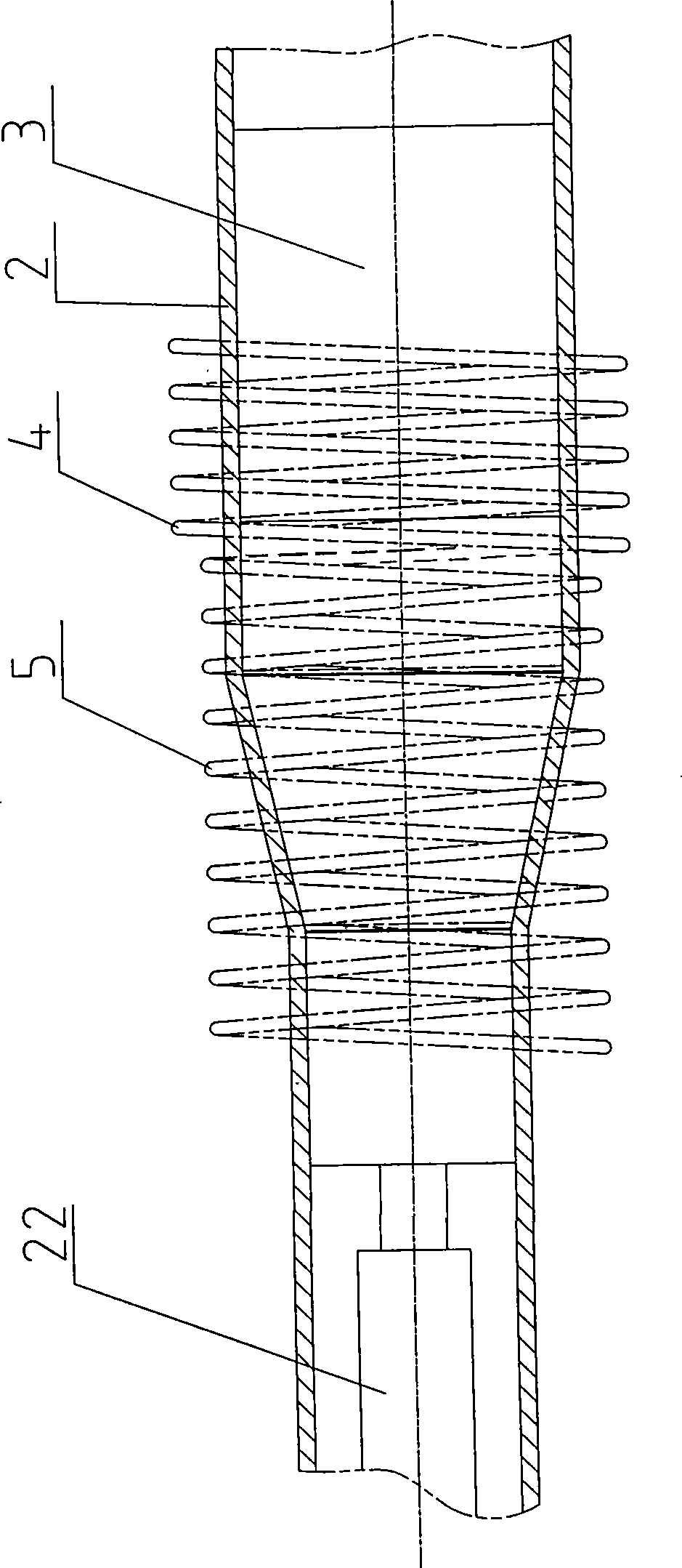
[0011] As shown in the accompanying drawings, the stainless steel pipe thermal expansion pipe making machine of the present invention includes a bracket 21, a support plate 17, a rear push plate 14, a front push plate 10, and a front support arranged sequentially on the base 15 from back to front. plate 7, the hydraulic cylinder 20 is fixed on the bracket 21 and the support plate 17, the rear push plate 14 is fixed on the front end of the plunger rod 16 on the hydraulic cylinder 20, one end of the push rod 11 is fixed on the rear push plate 14, and the other end is fixed On the front push plate 10, it is characterized in that there is a core mold support 1 in front of the front support plate 7, an intermediate frequency induction heating coil device 6 is arranged between the front support plate and the core ...


PUM

PropertyMeasurementUnit
Frequencyaaaaaaaaaa
Inductanceaaaaaaaaaa

Abstract

The invention provides a tube manufacturing machine for thermal diameter expansion of a stainless steel tube, and belongs to a steel tube processing device. The tube manufacturing machine comprises a bracket, a supporting plate, a rear push plate, a front push plate and a front supporting plate arranged on a stand sequentially from rear to front; an intermediate frequency heating coil of an intermediate frequency induction heating coil device consists of an induction heating coil section and a heat insulating coil section; a core head mould consists of a guide section, a diameter variation section, a diameter sizing section, a tapered section, and an alignment section from rear to front; and in the tube manufacturing machine for the thermal diameter expansion of the stainless steel tube, the structures of the core head mould and the intermediate frequency heating coil and a material of the core head mould are suitable for requirements on the thermal tube expansion of the stainless steel tube; the diameter of the stainless steel tube is arbitrarily enlarged and shaped, and the material and the wall thickness of the stainless steel tube after diameter expansion is unchanged. Simultaneously, the stainless steel tube after the diameter expansion reaches the requirement on normalizing, and improves a metallographic phase structure of the original stainless steel tube so as to improve the physical performance of the stainless steel tube after the diameter expansion and fully reach or exceed various indexes regulated by national standard.

Description

technical field [0001] The invention provides a steel pipe processing device, in particular a pipe making machine for stainless steel pipes. Background technique [0002] At present, the diameter of stainless steel pipes is as small as seamless stainless steel pipes. The largest domestic diameter is φ325mm, and the specifications and varieties based on diameter are not complete, so it is difficult to adapt to the application requirements of different diameters. But so far, there is no applicable stainless steel pipe thermal expansion pipe making equipment. The inventor once developed the hydraulic pressure two-step propelling pipe making machine that obtained the Chinese patent (the patent No. is ZL98221393.X), and successively developed a series of propelling pipe making equipment that obtained the Chinese patent. However, the above equipment is only suitable for the processing of carbon steel pipes such as diameter expansion. Because stainless steel has the characteristic...

Claims


Application Information

Patent Timeline
IPC IPC(8): B21C1/24B21C9/00B21C3/16B21D39/20B21D37/16B21D37/01
Inventor 付朋傅丙仲
Owner 付朋
Learn More