Illuminator structure for vehicle

A technology for illuminator and vehicles, which is applied to road vehicles, lighting devices, fixed lighting devices, etc. It can solve the problems of easy light diffusion of light bulbs, achieve uniform light distribution, improve commerciality, and inhibit diffusion

Active Publication Date: 2009-07-01
HONDA MOTOR CO LTD
View PDF1 Cites 3 Cited by
  • Summary
  • Abstract
  • Description
  • Claims
  • Application Information

AI Technical Summary

Problems solved by technology

[0004] However, in the above-mentioned prior art, light distribution is performed only on the bulb light leaking from the gap around the main reflector and the opening provided in the main reflector, so the bulb light is easy to diffuse, and it becomes a problem to ensure sufficient brightness.

Method used


Image

  • Illuminator structure for vehicle
  • Illuminator structure for vehicle
  • Illuminator structure for vehicle

Examples


Embodiment Construction

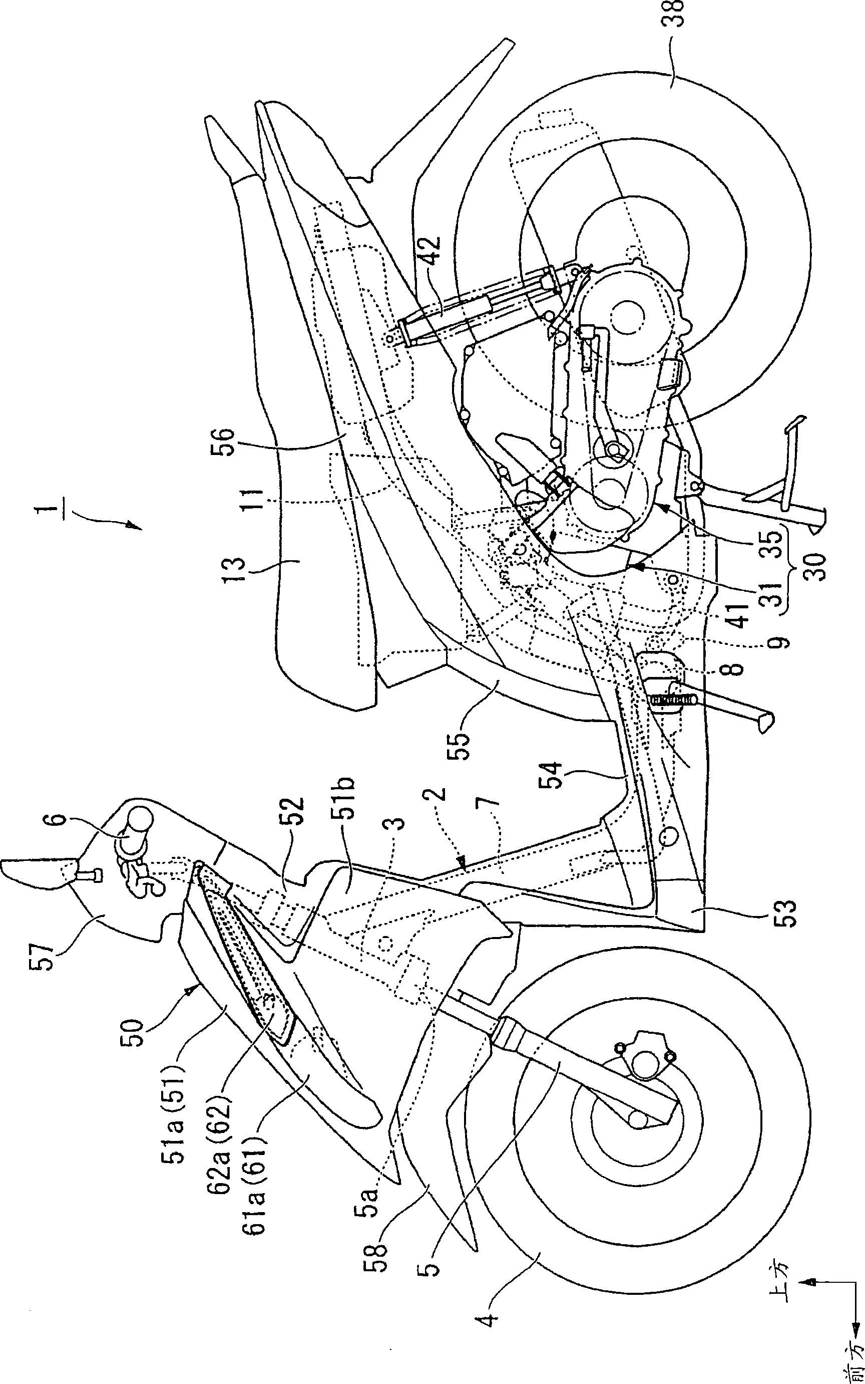
[0033] Hereinafter, embodiments of the present invention will be described with reference to the drawings. In the following description, the directions, such as front, rear, left, and right, are the same as the direction of the vehicle unless otherwise stated. The arrow FR in the figure indicates the front of the vehicle, the arrow LH indicates the left of the vehicle, and the arrow UP indicates the upper side of the vehicle.

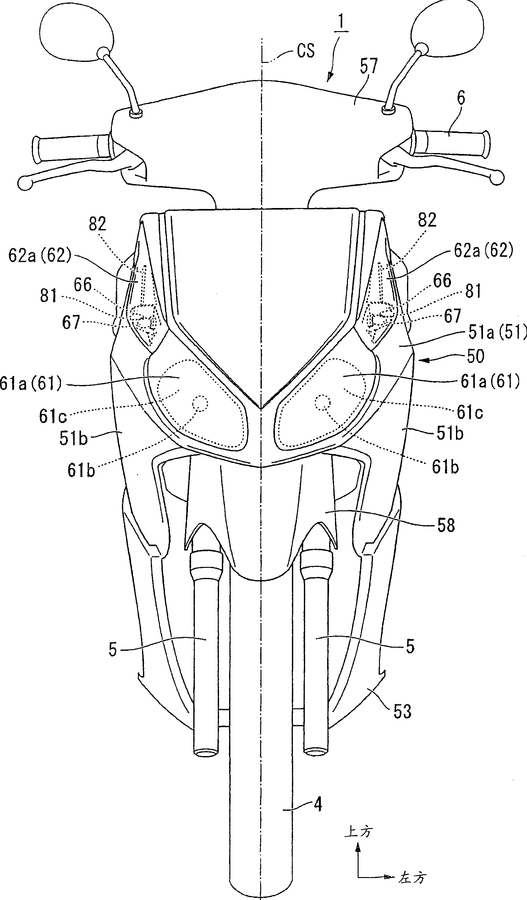
[0034] in figure 1 , 2 In the two-wheeled motor vehicle (saddle-riding vehicle) 1 of the scooter type shown, the left and right front forks 5 supporting the front wheels 4 are pivotally supported at the front end of the body frame 2 via a steering shaft 5a to be able to steer. Pipe 3 places. A steering handlebar 6 is attached to the upper part of the steering shaft 5a. figure 2 The middle line CS represents the center plane on the left and right of the car body.

[0035] The body frame 2 has a main frame 7 extending obliquely downward and rearward from th...


PUM


Abstract

A structure of vehicular illuminator can ensure enough brightness of bulb light transmitting to different directions and can execute reliable light distribution in the structure of vehicular illuminator which executes light distribution in the direction different from the reflection direction of main reflector. The structure of vehicular illuminator is provided with the following components: a notch (81) which is formed on a main reflector (67) and guides the bulb light to the back side of main reflector (67), and an auxiliary reflector (82) which extends to the back part of main reflector (67) along the irradiation direction of bulb light guided by the notch (81). The bulb light which passes through the notch (81) and is guided to the back part of main reflector (67) is executed with light distribution in a direction different from the reflection direction of main reflector (67) by the auxiliary reflector (82).

Description

Technical field [0001] The present invention relates to a vehicle illuminator structure suitable for motorcycles and the like. Background technique [0002] In the conventional vehicle illuminator structure of a motorcycle, some can distribute the light bulb light in a direction different from the reflection direction of the main reflector (for example, refer to Patent Document 1). [0003] Patent Document 1: (Japan) JP 2007-83894 A [0004] However, in the above-mentioned prior art, since only the bulb light leaked from the gap around the main reflector and the opening provided in the main reflector is distributed, the bulb light easily diffuses, and ensuring sufficient brightness becomes a problem. Summary of the invention [0005] The object of the present invention is to, in a vehicle luminaire structure that can also distribute the light bulb light in a direction different from the reflection direction of the main reflector, it is possible to ensure sufficient brightness of...

Claims


Application Information

Patent Timeline
Patent Type & Authority Applications(China)
IPC IPC(8): F21S8/10F21V7/04F21V7/10B62J6/00F21W101/027F21W107/17F21Y101/00
Inventor 段原崇中岛广幸滝本幸子久保田吉隆
Owner HONDA MOTOR CO LTD
Why Eureka
Try Eureka