Image stabilization control circuit

一种振动补偿、控制电路的技术,应用在通用控制系统、控制/调节系统、电视等方向,能够解决影响变大等问题,达到提高精度的效果

Inactive Publication Date: 2009-07-01
SANYO ELECTRIC CO LTD +1
View PDF1 Cites 4 Cited by
  • Summary
  • Abstract
  • Description
  • Claims
  • Application Information

AI Technical Summary

Problems solved by technology

In particular, the compensation frequency band B for the purpose of assuming the existence of a vibration component in order to compensate CMP In the case where the frequency region where the phase delay of the gyro sensor occurs is involved, the influence may become greater

Method used


Image

  • Image stabilization control circuit
  • Image stabilization control circuit
  • Image stabilization control circuit

Examples


Embodiment Construction

[0021] Hereinafter, modes for implementing the present invention (hereinafter referred to as embodiments) will be described with reference to the drawings. This embodiment relates to a camera, and the vibration compensation control circuit related to the present invention is used in the anti-shake function of the camera.

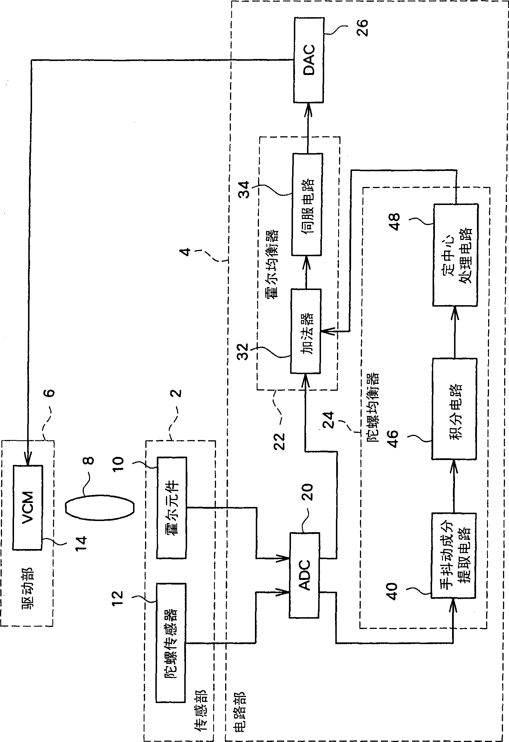
[0022] figure 1 It is a schematic block configuration diagram of the hand-shake compensation system of the camera according to the embodiment. This hand shake compensation system includes a sensor unit 2 , a circuit unit 4 , and a drive unit 6 . There are several types of hand-shake compensation systems. For example, this system can control the position of a correction lens (lens 8 ) provided in an optical system that forms an optical image on a photosensitive surface of an imaging element (not shown).

[0023] The sensor unit 2 is composed of a Hall element 10 and a gyro sensor 12 . The Hall element 10 is a sensor provided for detecting the position of ...


PUM


Abstract

In the vibration compensation control circuit of a camera device, the detected angular velocity signals corresponding to the vibration are integrated to acquire the required displacement of a lens. In the processing, the output signal of a gyro sensor is impacted by phrase delay generated in a high frequency area; therefore, the high-frequency area generates surplus phrase delay, a correct integral signal is hard to acquire and the vibration compensation accuracy is low. The invention provides a vibration compensation control circuit. A gyro equalizer (24) integrates the angular velocity signals from the gyro sensor (12) by an integral circuit (46) and converts the angular velocity signals into angle signals, and then a centering processing circuit (48) (HPF) removes the direct current components of the angle signals. A low boost filter (LBF) is adopted to form the integral circuit (46) to take the phrase delay of a target compensation frequency band as the value corresponding to the integral processing. Furthermore, by means of the property of reducing phrase delay, the LBF compensates the surplus phrase delay of the angle signals in the high-frequency area caused by the phrase property of the gyro sensor (12) on the high frequency side and leads the phrase delay in the high frequency area to be close to 90 degrees.

Description

technical field [0001] The present invention relates to a vibration compensation control circuit for driving a vibration compensation mechanism provided for compensating vibration such as hand shake in an imaging device such as a digital still camera. Background technique [0002] An anti-shake function for suppressing deterioration of image quality due to hand-shake is installed in many imaging devices in recent years. There are many methods of hand shake compensation, among which there is a method in which the vibration detection element detects the vibration of the imaging device, and based on the detection signal, the optical components such as the correction lens and the CCD image sensor are adjusted by the actuator. The imaging element is displaced. The vibration detection element adopts a gyro sensor to detect an angular velocity corresponding to a change in the direction of the optical axis. On the other hand, for the drive control of the actuator, the displacement...

Claims


Application Information

Patent Timeline
Patent Type & Authority Applications(China)
IPC IPC(8): G03B5/00H04N5/232
CPCG03B5/00G02B7/02G05B5/01G02B27/646G03B2205/0007H04N23/683
Inventor 永田康宣山田恭久田下裕树
Owner SANYO ELECTRIC CO LTD
Why Eureka
Try Eureka