
Anti-interference sound equipment line

A technology for audio line and signal interference, applied in the direction of circuit lead arrangement/elimination, conductors, insulated cables, etc., can solve the problems of signal interference, signal distortion, signal distortion, etc., to achieve easy to use, good signal transmission, not easy to break Effect

Inactive Publication Date: 2009-07-01
SHENZHEN LIANJIAXIANG SCI & TECH
View PDF0 Cites 3 Cited by
  • Summary
  • Abstract
  • Description
  • Claims
  • Application Information

AI Technical Summary

Problems solved by technology

However, the internal circuit and the outside of the audio cable are easily affected by interference, especially the general audio cable is arranged together with the power cable, so it will generate a magnetic field that interferes with each other. These interferences will affect the transmission quality of the signal, resulting in signal distortion or signal loss. distortion
A good audio cable requires good signal transmission performance (mainly completed by the core and terminals), better insulation and shielding functions (completed by the insulating layer and shielding layer), so that it can really play the role of high-fidelity transmission of audio signals, but the existing The effect of the shielding layer in the technology is not very good, and it cannot meet the needs of people's increasingly high requirements
[0003] Based on the shortcomings of the above-mentioned existing audio cables, the inventor designed "an anti-interference audio cable" for solving signal interference and distortion.

Method used


Image

  • Anti-interference sound equipment line
  • Anti-interference sound equipment line

Examples


Embodiment Construction

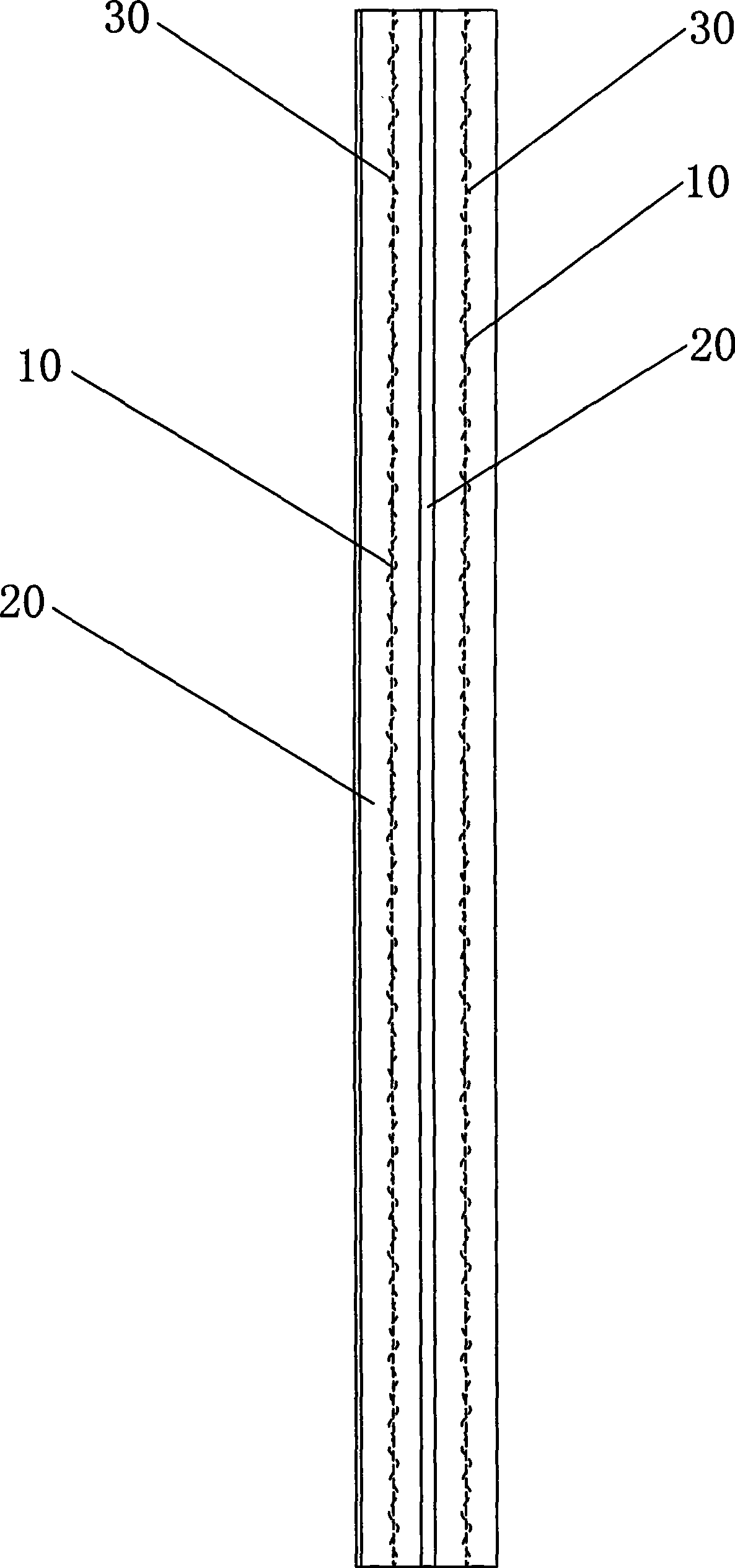
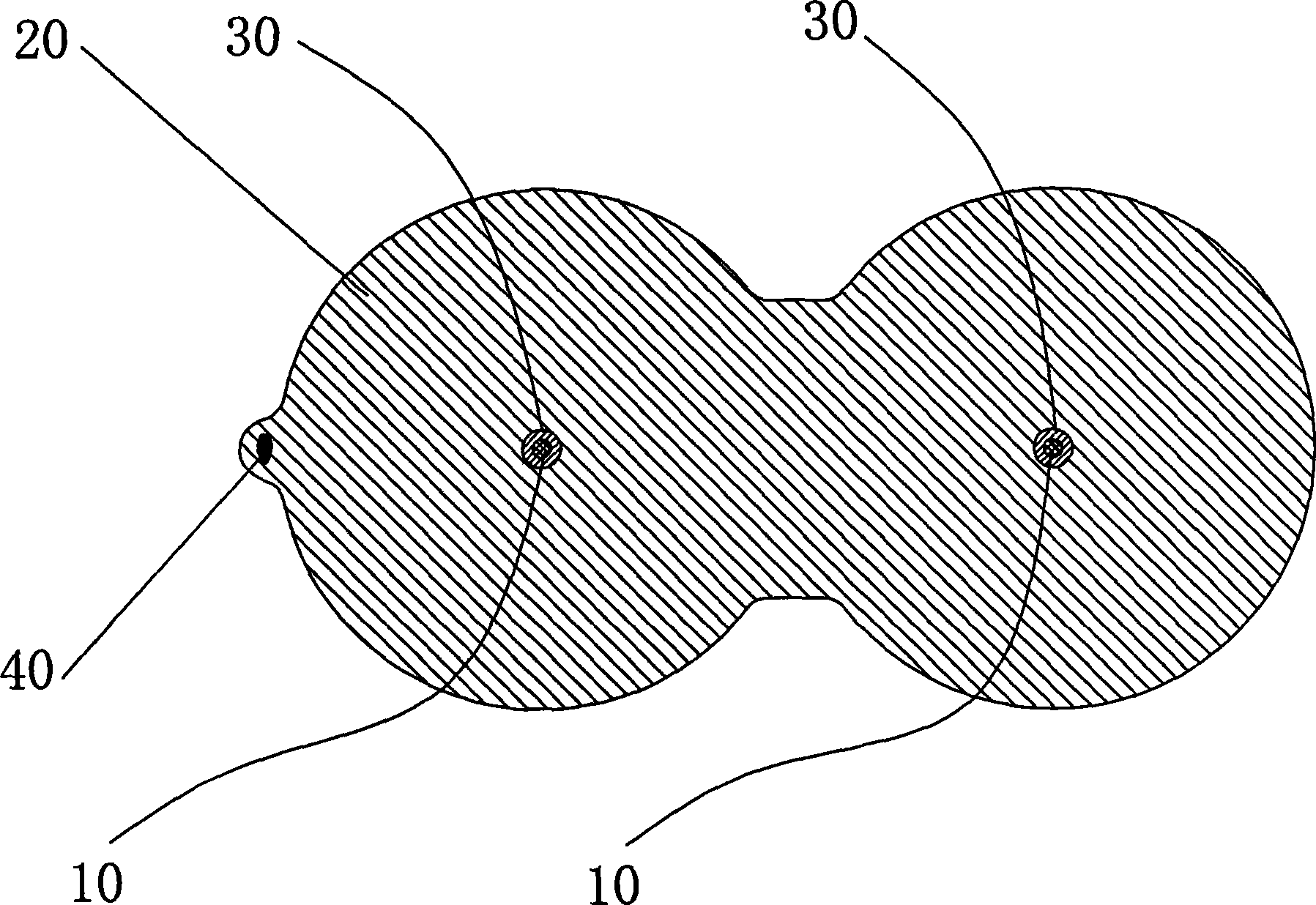
[0021] refer to Figure 1 to Figure 2 , the present invention is implemented like this:

[0022] exist figure 1 with figure 2 Among them, an anti-interference audio cable includes a conductor (10) twisted by a plurality of thin copper wires and a PVC sheath (20) wrapped outside the conductor (10), the conductor (10) and the PVC sheath ( 20) are wound with an aluminum foil shielding layer (30) that resists external magnetic field interference and reduces the interference of the conductor (10) transmitting signals.

[0023] In the present embodiment, the thickness of the aluminum foil shielding layer (30) is 0.025mm, and its overlapping ratio is 30%, and the aluminum foil shielding layer (30) formed by winding the overlapping ratio of 30% is relatively tight, because the aluminum foil shielding layer (30) The thickness is thin and it is not easy to break during bending. The PVC sheath (20) is a transparent PVC sheath, and the PVC sheath (20) is covered with two conductors (...


PUM

PropertyMeasurementUnit
Thicknessaaaaaaaaaa
Diameteraaaaaaaaaa

Abstract

The invention relates to an audio cable, in particular to the audio cable which has good transmission signal effect and resists interference. The audio cable comprises a plurality of conductors formed by weaving fine brass wires and PVC protective layers packed outside the conductors, wherein an aluminum foil shielding layers are wound between the conductors and the PVC protective layers, the aluminum foil shielding layers are provided with the function of resisting external interference, prevent signals which are transmitted by the conductors from interference, and the aluminum foil shielding layers formed from winding has good effect of shielding interference and effect, wherein the thickness of aluminum foil is 0.025 mm. The audio cable has beneficial effects that firstly, solving the problem of the interference of a magnetic field, which is generated when a power source line and an audio line are arranged together, providing the audio cable which is beautiful and convenient for use, and has good transmission signals, secondly, solving the effect of inner loops of the audio cable and the external interference, the effects of shielding the electromagnetic interference and the effect are better, the aluminum foil shielding layer is quite compact, since the thickness of the aluminum foil shielding layer is thinner, the aluminum foil shielding layer is not easily broken during the process of bending materials.

Description

technical field [0001] The invention relates to an audio cable, in particular to an anti-interference audio cable with good signal transmission effect. Background technique [0002] Existing sound wire generally all is made of four parts of middle core (also called " conductor "), insulating layer (also called PVC plastic protective layer), shielding layer and connecting terminal. Conductor: Generally, it is made of multiple (also called "multi-branches") oxygen-free copper or silver-plated copper with small wire diameters twisted by a high-speed stranding machine. The size of the wire core is determined according to national standards and actual needs. PVC plastic protective layer: In order to avoid unnecessary contact between the wire core and the metal shielding layer or between the metal shielding layer and the outside world, a rubber isolation layer is "pressed" on the surface of the wire core or the shielding layer by the extrusion unit , We call it the insulation lay...

Claims


Application Information

Patent Timeline
IPC IPC(8): H01B11/06H01B7/17H04R1/06
Inventor 黄冬莲
Owner SHENZHEN LIANJIAXIANG SCI & TECH
Learn More