
Cross polarization antenna

A cross-polarization and antenna technology, applied in antennas, antenna arrays, antenna combinations with different interactions, etc., can solve the problems of difficult manufacturing and assembly processes, different polarization directions, and complex antenna structures, and achieve the goal of manufacturing and assembly. Convenience, polarization loss reduction, effect of reducing polarization loss

Inactive Publication Date: 2009-07-01
SMARTANT TELECOMM
View PDF0 Cites 2 Cited by
  • Summary
  • Abstract
  • Description
  • Claims
  • Application Information

AI Technical Summary

Problems solved by technology

[0007] In order to solve the problems of polarization loss caused by the different polarization directions of the antenna and the electromagnetic wave it receives, and the complex structure of the antenna makes the manufacturing and assembly process difficult, the present invention proposes a cross-polarized antenna, which can effectively receive various Electromagnetic waves in the polarization direction, and through the integrated design, make manufacturing and assembly more convenient, thus reducing manufacturing costs

Method used


Image

  • Cross polarization antenna
  • Cross polarization antenna
  • Cross polarization antenna

Examples


Embodiment Construction

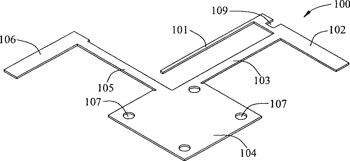
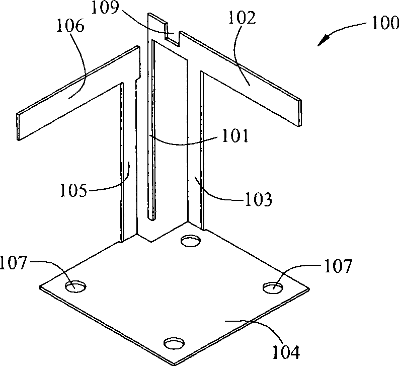
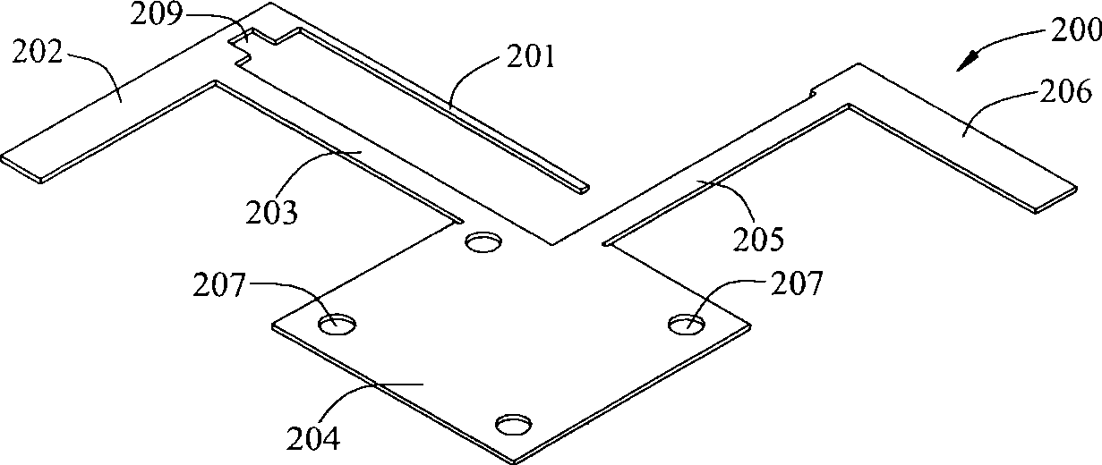
[0057] The cross-polarized antenna disclosed in the present invention is mainly composed of a first cross-polarized antenna 100 and a second cross-polarized antenna 200 , a substrate 300 , a first impedance converter 400 and a second impedance converter 500 . First, the structure and composition of the first cross-polarized antenna 100 will be described.

[0058] Please refer to figure 1 and figure 2 . The first cross-polarized antenna 100 of the present invention includes a first transmission part 101 , a first radiation part 102 , a first ground part 103 , a first bottom surface 104 , a second ground part 105 and a second radiation part 106 . Wherein, the first transmission part 101, the first radiation part 102, the first ground part 103, the first bottom surface 104, the second ground part 105 and the second radiation part 106 are made of conductive material, and the conductive material can be But not limited to metals. On the other hand, the first transmission part 1...


PUM


Abstract

A cross polarization antenna comprises a substrate, a first impedance converter, a second impedance converter, a first cross polarization antenna and a second cross polarization antenna, wherein the first opening of the first cross polarization antenna is corresponding to the second opening of the second cross polarization antenna, and can be spatially arranged crosswise without contacting with each other. The cross polarization antenna can effectively receive electromagnetic waves from various polarization directions to reduce polarization loss, and is fabricated integrally to achieve convenient fabrication and assembly and low fabrication cost.

Description

technical field [0001] The invention relates to an antenna, in particular to a cross-polarized antenna which is formed by intersecting two integrally formed antennas. Background technique [0002] The radio frequency signal output by the radio transmitter is transmitted to the antenna through the feed line, and the antenna radiates to the outside world in the form of electromagnetic waves. When the electromagnetic wave is transmitted to the receiving point, the electromagnetic wave is received by the antenna, and then the radio frequency signal is transmitted to the radio receiver through the feed-in line. [0003] Generally speaking, the antenna radiates electromagnetic waves to the surroundings, and the electromagnetic waves are composed of an electric field and a magnetic field, wherein the direction of the electric field is the polarization direction of the antenna. Therefore, the electromagnetic waves that antennas with different polarization characteristics can receiv...

Claims


Application Information

Patent Timeline
Patent Type & Authority Applications(China)
IPC IPC(8): H01Q21/00H01Q21/29
Inventor 林作华
Owner SMARTANT TELECOMM
Learn More