
Apparatus and method for ablating tissue

A tissue and ablation element technology, applied in the direction of heating surgical instruments, parts of surgical instruments, medical science, etc., can solve problems such as damage, difficult pulmonary vein injury geometry, incomplete surrounding pulmonary veins, etc., and achieve the effect of accelerating the recovery process

Inactive Publication Date: 2009-07-01
ST JUDE MEDICAL ATRIAL FIBRILLATION DIV
View PDF12 Cites 12 Cited by
  • Summary
  • Abstract
  • Description
  • Claims
  • Application Information

AI Technical Summary

Problems solved by technology

Second, typical elongated and flexible endovascular ablation devices are difficult to form into the complex geometries required to create pulmonary vein lesions while maintaining this position against the wall of the beating heart
Therefore, the procedure is time consuming and may produce lesions that do not completely surround the pulmonary veins or contain septa or discontinuities

Method used


Image

  • Apparatus and method for ablating tissue
  • Apparatus and method for ablating tissue
  • Apparatus and method for ablating tissue

Examples


Embodiment Construction

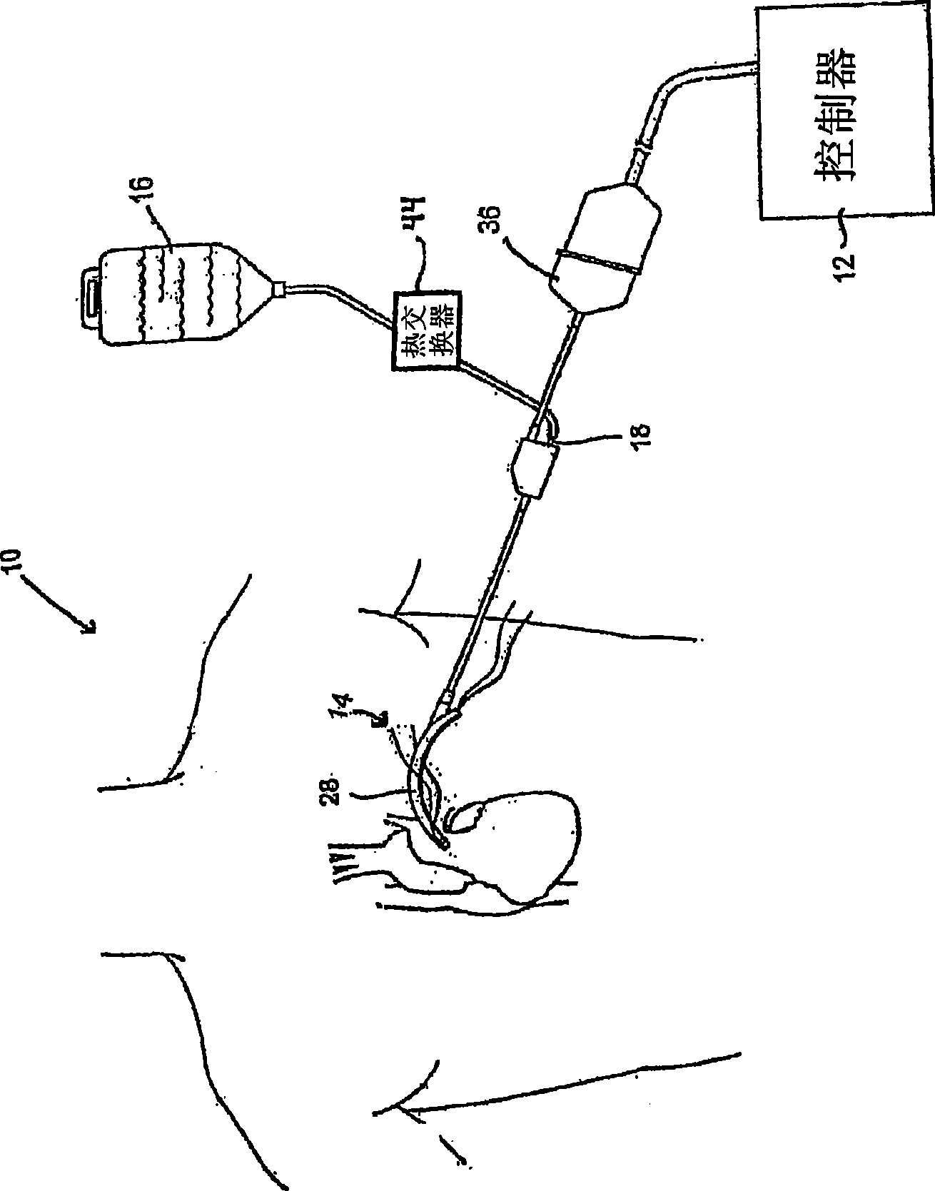
[0048] now refer to figure 1 , this figure represents an ablation system 10 according to one embodiment of the present invention. The ablation system 10 includes a controller 12, which is preferably used to provide focused ultrasound energy. Ablation system 10 may be used to surround a pulmonary vein at an epicardial location to create a pulmonary vein (PV) isolated ablation lesion. The ablation system 10 may also include a source 16 of flowable material, which may be a saline bag that provides a gravity-fed fluid supply to the ablation device 14 through a standard luer connector 18 . .

[0049] The system also includes an introducer 20 (shown in figure 2 and image 3 ), the introducer 20 is advanced around the pulmonary vein, as Figure 7 and Figure 8 shown, will be explained below. like figure 2 As shown, the introducer 20 preferably forms a substantially closed loop in an unbiased configuration with a small offset near its distal end 22, as shown in image 3 sho...


PUM


Abstract

A device for ablating cardiac tissue includes a plurality of ablation elements substantially aligned along a common axis and adjustable between first and second predetermined positions. In the first predetermined position, the plurality of ablation elements form a curved contact surface. In the second predetermined position, the plurality of ablation elements form a substantially straight insertion configuration. At least one hinge (27) may connect adjacent ones of the plurality of ablation elements (26). Each of the plurality of ablation elements may be located within a housing (29), which may have at least a portion of a hinge integrally formed therewith to connect adjacent ablation elements. Alternatively, a strand of superelastic material (38), such as a Nitinol wire, may interconnect ablation elements. The superelastic material may bias the plurality of ablation elements into at least one of the first and second predetermined positions.

Description

[0001] Cross References to Related Applications [0002] This application claims priority to US Provisional Application No. 60 / 815,852, filed June 23, 2006 (the '852 application). This application also claims priority to now-pending US Nonprovisional Patent Application No. 11 / 646,526, filed December 28, 2006 (the '526 application). Both the '852 application and the '526 application mentioned above are incorporated herein by reference. [0003] This application is related to the following applications filed June 23, 2006: U.S. Provisional Application No. 60 / 815,853, U.S. Provisional Application No. 60 / 815,880, U.S. Provisional Application No. 60 / 815,881, and U.S. Provisional Application No. 60 / 815,882. These applications are incorporated herein by reference. [0004] This application is also related to U.S. Application Nos. 11 / 401,345 and 11 / 401,357, filed April 11, 2006, which were filed on September 24, 2002 A continuation of U.S. Application No. 10 / 255,134 (now U.S. Paten...

Claims


Application Information

Patent Timeline
IPC IPC(8): A61B18/14
CPCA61B2018/0016A61B18/1492A61B2018/00363A61B2018/00577
Inventor J·E·克洛维J·L·博德默尔M·霍尔兹鲍尔
Owner ST JUDE MEDICAL ATRIAL FIBRILLATION DIV
Learn More