Low-pressure gas discharge lamp

A technology for low-pressure gas and discharge lamps, which can be applied to parts, luminescent materials, chemical instruments and methods of gas discharge lamps, and can solve problems such as motion artifacts.

Inactive Publication Date: 2009-07-01
KONINKLIJKE PHILIPS ELECTRONICS NV
View PDF0 Cites 1 Cited by
  • Summary
  • Abstract
  • Description
  • Claims
  • Application Information

AI Technical Summary

Problems solved by technology

[0006] Motion artifacts can still occur in known LCD panels with backlight units comprising low-pressure gas discharge lamps used in scanning or flashing modes of operation

Method used


Image

  • Low-pressure gas discharge lamp
  • Low-pressure gas discharge lamp
  • Low-pressure gas discharge lamp

Examples


Embodiment Construction

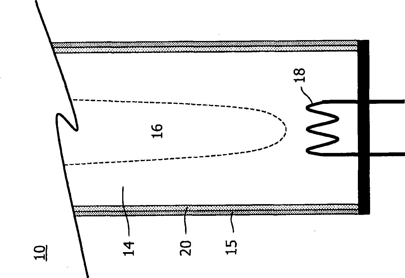
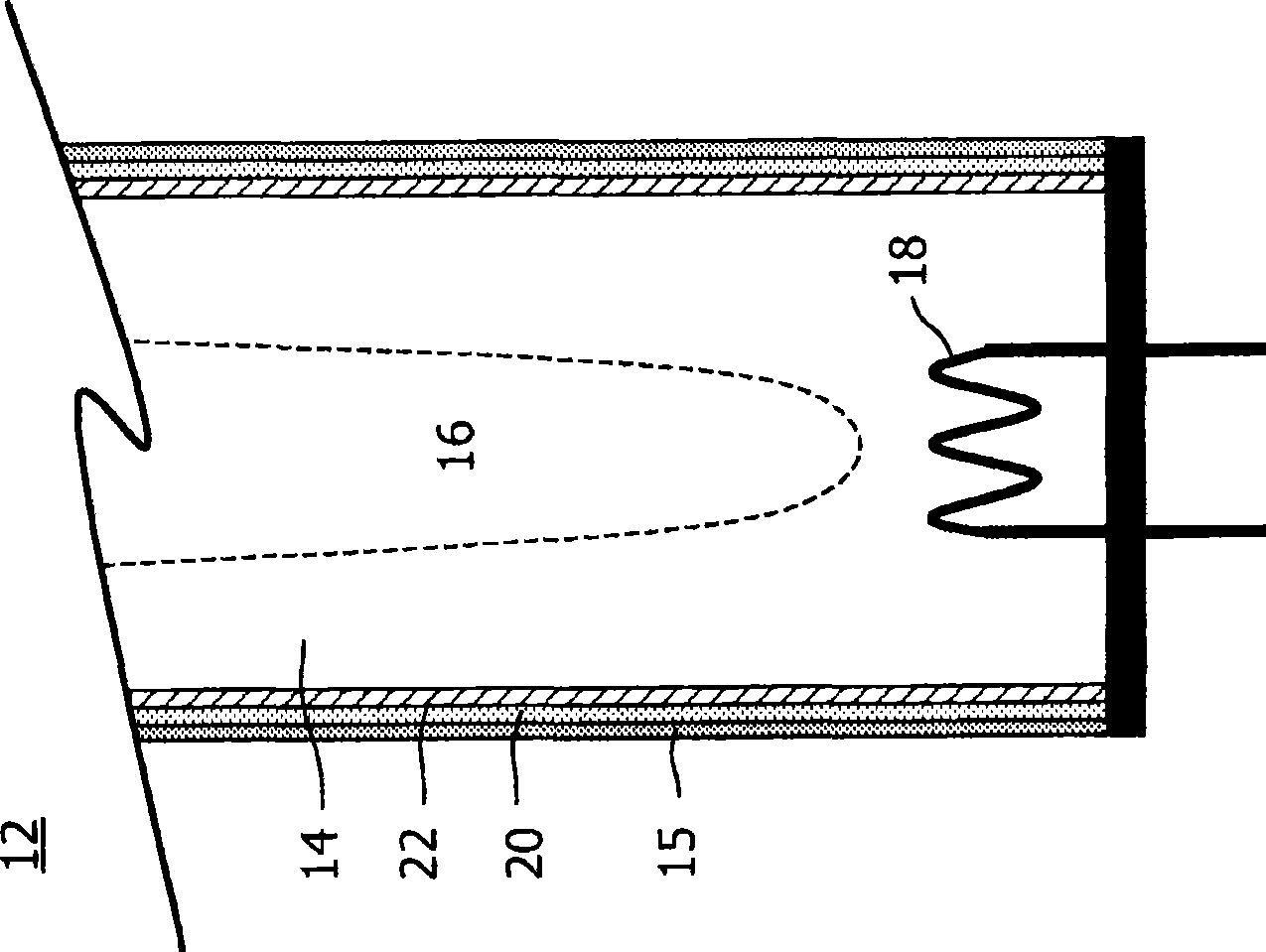
[0029] Figure 1A with 1B A cross-sectional view of a low-pressure gas discharge lamp 10, 12 according to the invention is shown. The low-pressure gas discharge lamp 10, 12 according to the invention comprises a light-transmissive discharge vessel 14, which seals off a discharge space 16 in a gas-tight manner. The discharge space 16 includes a gas filling, which includes, for example, metal compounds and buffer gases. The low-pressure gas discharge lamp 10, 12 further comprises a coupling element. The coupling element couples energy into the discharge space 16 , for example via capacitive coupling, inductive coupling, microwave coupling or via the electrodes 18 , in order to effect a gas discharge in the discharge space 16 . The discharge vessel 14 comprises a wall 15 having a luminescent layer 20 comprising a luminescent material. The luminescent material absorbs, for example, ultraviolet light emitted by the discharge and, for example, converts the absorbed ultraviolet li...


PUM


Abstract

The invention relates to a low-pressure gas discharge lamp (10) for use in a scanning or blinking backlighting system, the low-pressure gas discharge lamp (10) comprising a luminescent layer (20) comprising a luminescent material selected from a group comprising: (Sr1-x-y-z, Bax, Cay, Eu(II)z)2Si04 (also known as XSO), (Sr1-x-y-z, Bax, Cay, Eu(II)z)Si2N2O2 (also known as XSON), and (Sr1-x-y-z, Bax, Cay, Eu(II)z)2Si5N8 (also known as XSN), wherein 0=x<1, 0=y<, 0<z=0.20, and x+y+z=l. The luminescent materials according to the invention have a relatively short decay time (less than 0.5 milliseconds), resulting in a relatively short afterglow time of the low-pressure gas discharge lamp (10) according to the invention. When using known low- pressure gas discharge lamps, for example, comprising the luminescent materials BAM, LAP and YOX in the scanning or blinking backlighting system, the afterglow time of these luminescent materials creates visible motion artifacts, especially when the scanning or blinking time is increased from 50 Hertz or 60 Hertz to, for example, 90 Hertz or 100 Hertz. Replacing the known luminescent materials LAP and/or YOX with luminescent material according to the invention will result in a reduction of the motion artifacts.

Description

technical field [0001] The invention relates to a low-pressure gas discharge lamp for a backlight system, which is set to work in a scanning mode or a flashing mode. Background technique [0002] Low-pressure gas discharge lamps generally comprise a discharge vessel with a luminescent layer comprising a luminescent material. The luminescent layer is generally applied to the inner wall of the discharge vessel. The luminescent material converts the UV light emitted from the discharge space into light of increased wavelength (typically visible light), which is subsequently emitted by the low-pressure gas discharge lamp. Such discharge lamps are also called fluorescent lamps. Low-pressure gas discharge lamps for general lighting purposes generally comprise a mixture of luminescent materials, wherein the combination of said luminescent materials determines the color of the light emitted by the fluorescent lamp. Examples of commonly used luminescent materials are, for example, ...

Claims


Application Information

Patent Timeline
Patent Type & Authority Applications(China)
IPC IPC(8): C09K11/77H01J61/44
Inventor W·J·M·施拉马A·A·S·斯卢伊特曼
Owner KONINKLIJKE PHILIPS ELECTRONICS NV
Why Eureka
Try Eureka