

Backpack medlar-picking machine
A picking machine and knapsack technology, applied in the field of knapsack wolfberry picking machines, can solve the problems of damage to fruits and branches and leaves, and achieve the effects of reducing damage, novel structure, and convenient movement
- Summary
- Abstract
- Description
- Claims
- Application Information
AI Technical Summary
Problems solved by technology
Method used
Image

Examples
Embodiment Construction
[0013] The present invention will be described in detail below in conjunction with the accompanying drawings and embodiments.
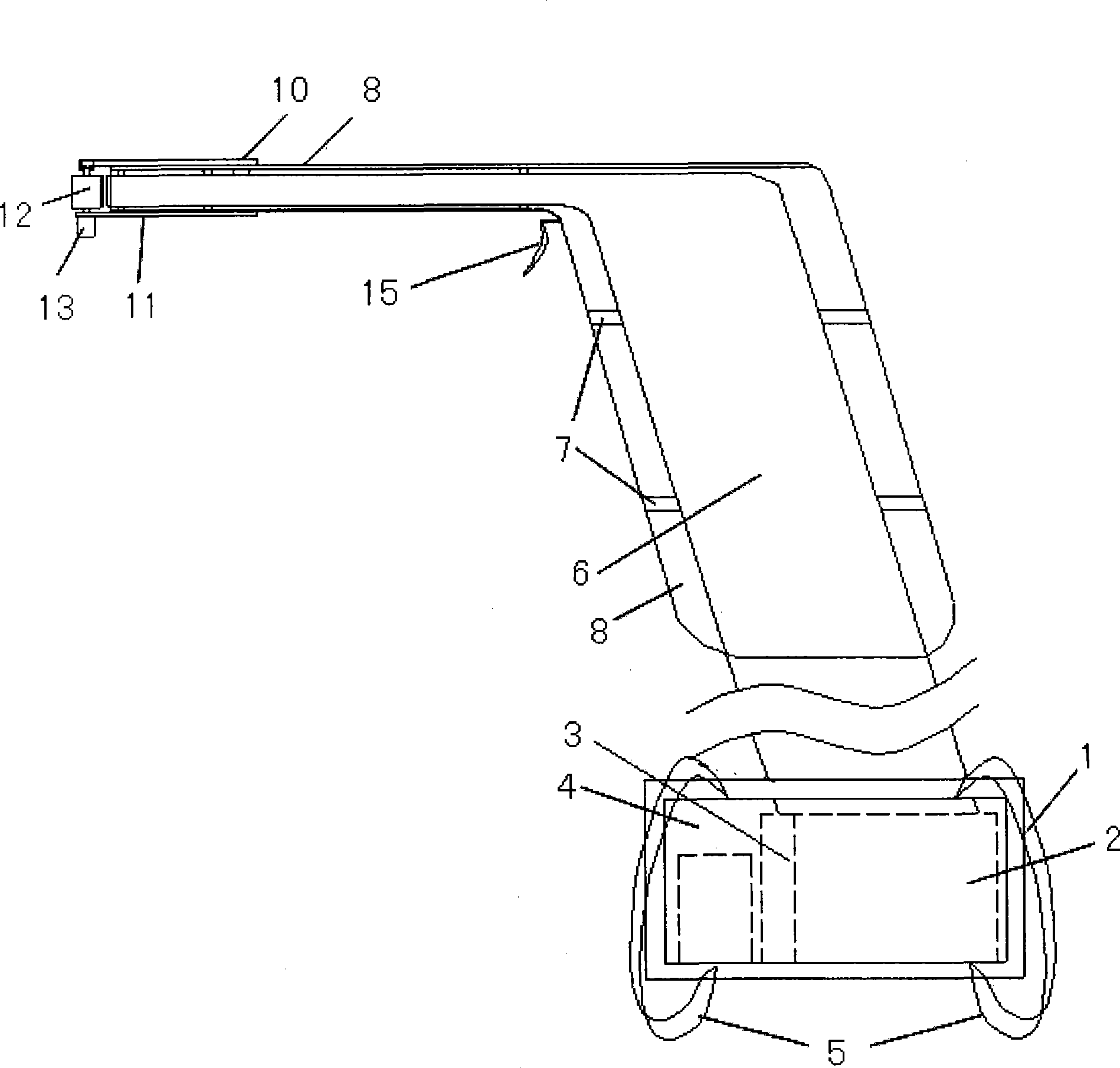
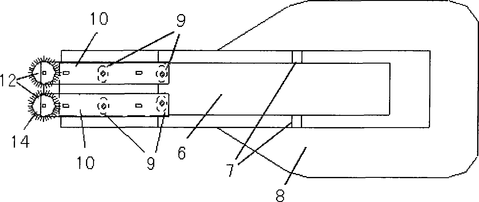
[0014] Such as figure 1 , figure 2 Shown, the present invention adopts the structural form that carries on the back and adds hand-held combination, and it comprises a backpack box 1, and backpack box 1 adopts hard light material to make, as aluminum plate. A fruit collection box 2, an electric exhaust fan 3 and a storage battery 4 are placed in the backpack 1; two straps 5 are fastened outside the backpack 1. The air outlet of the electric blower 3 communicates with the fruit collection box 2, so that the fruit collection box 2 can generate negative pressure. There is another entrance on the fruit collection box 2, which communicates with a soft straw 6 that penetrates the backpack box 1. The soft straw 6 has a certain length and is suitable for wolfberry plants of different heights. A plurality of brackets 7 are arranged on the periphery of the ...
PUM
 Abstract
Description
Claims
Application Information