Nitrogen purging device of hydraulic line and method for cleaning hydraulic line

A technology for hydraulic pipelines and nitrogen purging, which is used in cleaning methods and utensils, cleaning hollow objects, chemical instruments and methods, etc. Waste manpower, material and financial resources, etc., to achieve the effect of preventing and controlling secondary pollution, saving manpower and saving construction period

Inactive Publication Date: 2009-07-15
CHINA 19TH METALLURGICAL CORP
View PDF0 Cites 25 Cited by
  • Summary
  • Abstract
  • Description
  • Claims
  • Application Information

AI Technical Summary

Problems solved by technology

[0003] First, due to the high viscosity of the oil used for flushing, many impurities adhere to the inner wall of the pipeline, so the flushing effect achieved is very poor. Although the cleanliness level of the oil meets the requirements of the hydraulic system, there are still impurities in the pipeline that cannot clean up
[0004] Second, due to the secondary disassembly and flushing of the pipeline, it is easy to cause secondary pollution to the pipeline, and the pollution of the factory building is serious. The residual flushing oil after the primary oil flushing has relatively strong adhesion, and all impurities adhere to the inner wall of the pipeline.
[0005] Third, the flushing cycle is long, requiring two flushes in succession, and one oil flushing needs to bypass the precision equipment, which wastes a lot of manpower (a lot of labor is needed to configure a temporary flushing circuit), material resources (need to configure flushing A large number of pipes, pipe fittings, filter elements and flushing oil), financial resources (it takes a lot of money to buy temporary pipe fittings and welding materials for flushing)
[0006] Its four, cause pollution to the environment, owing to the inevitable existence leakage in the flushing process (refueling before flushing, oil discharge after flushing), residual waste oil is everywhere on the ground
[0007] In this way, it will be put into use after flushing, which will greatly reduce the service life of the hydraulic control valve and its pump group. At present, what new flushing method is used has become the focus of attention.

Method used


Image

  • Nitrogen purging device of hydraulic line and method for cleaning hydraulic line

Examples


Embodiment Construction

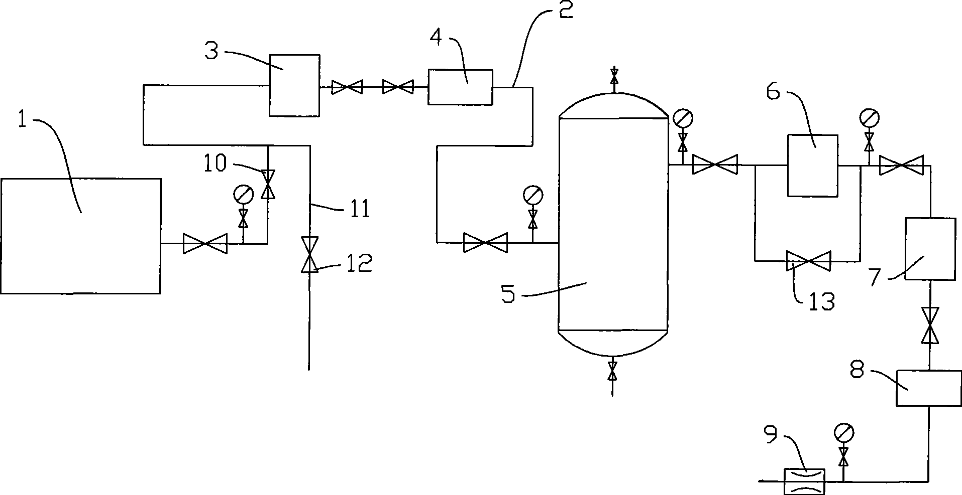
[0023] The nitrogen purge device used in the hydraulic pipeline in the figure, on the output pipeline 2 connected with the PSA nitrogen generator (nitrogen source) 1, there are in series a shut-off valve 10, a gas drying device 3, a gas filtering device 4, a gas storage Tank 5, gas pressurization device 6, gas drying device 7, gas filtering device 8, flow regulating valve 9. A branch 11 is bypassed on the output pipeline between the stop valve 10 and the gas drying device 3 , and a stop valve 12 is connected in series on the branch 11 . The shut-off valve 13 is connected in parallel with the gas pressurization device 6 .

[0024] During use, the shut-off valves 12 and 13 are closed, and the nitrogen separated from the PSA nitrogen generator passes through the shut-off valve 10, is dried by the gas drying device 3, is filtered by the gas filter device 4, and flows into the gas storage tank 5. The nitrogen gas flowing out from the gas storage tank 5 is pressurized by the gas bo...


PUM


Abstract

The invention provides a device and a method for cleaning hydraulic pipelines, in particular to a nitrogen purging device (cleaning device) for hydraulic pipelines, which has good cleaning effect, high efficiency and not pollution. The nitrogen purging device for hydraulic pipelines adopts the structure that a gas drier used for the drying treatment of nitrogen, a gas filter used for the filtering treatment of nitrogen and a flow control valve used for regulating the output flow of nitrogen are connected in series on an output pipeline which is connected with a nitrogen source. In addition, the cleaning method for hydraulic pipelines adopts nitrogen after being dried and filtered to purge the hydraulic pipelines.

Description

technical field [0001] The invention relates to a nitrogen purging device for hydraulic pipelines and a hydraulic pipeline cleaning method. Background technique [0002] For traditional hydraulic system pipelines, after the entire pipeline construction is completed, the pipeline needs to be flushed and cleaned. The traditional cleaning method is to first perform an oil flushing outside the line and a secondary oil flushing of the system. During primary oil flushing, due to the large amount of impurities, in order to prevent damage to precision equipment (such as pump sets and control valves), these precision equipment should be bypassed. After the primary flushing, restore the system pump equipment and control valves, and then carry out the secondary oil flushing of the system. This flushing method has the following disadvantages: [0003] First, due to the high viscosity of the oil used for flushing, many impurities adhere to the inner wall of the pipeline, so the flushin...

Claims


Application Information

Patent Timeline
Patent Type & Authority Applications(China)
IPC IPC(8): B08B9/032
Inventor 王卫东贾玲袁春阳
Owner CHINA 19TH METALLURGICAL CORP
Why Eureka
Try Eureka