
Double-wire bonding control method based on CAN bus

A technology of CAN bus and control method, applied in the direction of manufacturing tools, welding equipment, arc welding equipment, etc., can solve the problems of unstable welding process and irregular weld formation, achieve stable welding, good weld formation, and reduce interference Effect

Inactive Publication Date: 2009-07-15
SHANGHAI HUGONG ELECTRIC WELDING MACHINE MFG
View PDF0 Cites 16 Cited by
  • Summary
  • Abstract
  • Description
  • Claims
  • Application Information

AI Technical Summary

Problems solved by technology

[0003] However, due to the very close spatial distance between the two DC arcs during twin wire welding, if appropriate control measures are not taken, the electromagnetic interference between them will be very serious, resulting in unstable welding process and irregular weld formation.

Method used


Image

  • Double-wire bonding control method based on CAN bus

Examples


Embodiment Construction

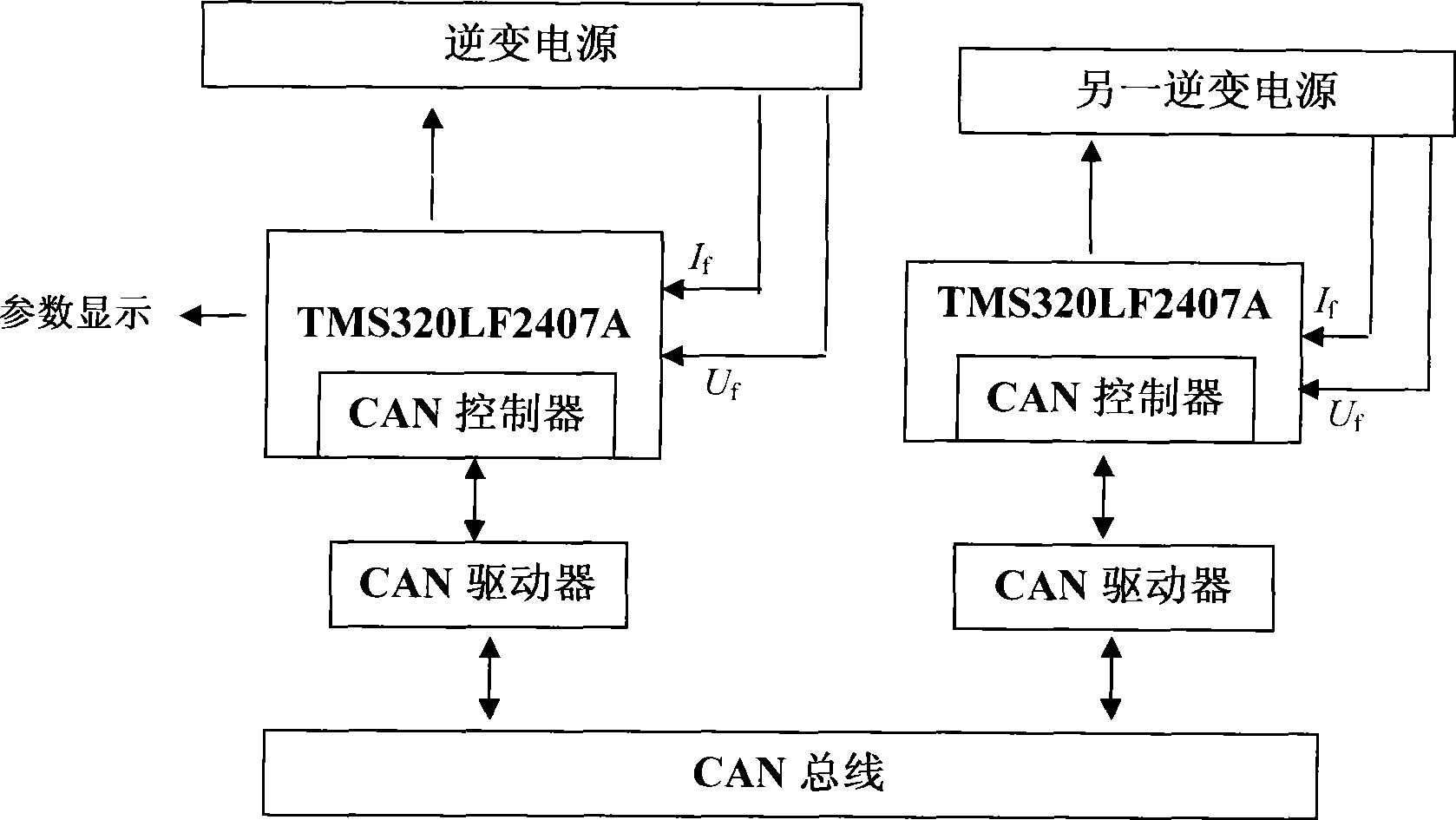
[0018] The CAN bus-based twin wire welding control method of the present invention will be further described in detail below.

[0019] see figure 1 Shown, the double wire welding control method based on CAN bus of the present invention, it comprises steps:

[0020] 1) When the first welding wire enters the base value state from the peak value state, at the peak falling edge stage, the first DSP chip controlling the first welding wire through the second power supply sends out the first trigger signal, and the first trigger signal passes through the CAN bus To the second DSP chip controlling the second welding wire by the second power supply, the second welding wire enters the peak state; 2) when the second welding wire value state ends, the second DSP chip sends the second trigger signal at the peak falling edge stage , the second trigger signal is sent to the first DSP chip via the CAN bus, and the first welding wire enters the peak state again; 3) Repeat steps 1) and 2).

...


PUM


Abstract

The invention relates to a dual-wire-welding control method based on a CAN bus, comprising the following steps: (1) when a first welding wire changes from a peak status to a base status, a second power supply controls a first DSP chip of the first welding wire to send out first triggering signals to a second DSP chip of a second welding wire controlled by a second power supply through the CAN bus, and the second welding wire enters the peak status; (2) after the second welding wire status is ended, the second DSP chip sends out second triggering signals to the first DSP chip through the CAN bus, and the first welding wire returns to the peak status again; and (3) the steps (1) and (2) are repeated. The invention maintains the phase difference of the output pulse welding current at 180 DEG, effectively reduces the interference between two arcs, achieves stable welding, increases the welding speed greatly while favorable welding line formation is obtained, achieves highly efficient welding and improves the production efficiency.

Description

technical field [0001] The invention relates to the technical field of a welding machine control method, in particular to the technical field of a twin-wire welding control method, in particular to a CAN bus-based twin-wire welding control method. Background technique [0002] With the rapid development of welding technology, the pursuit of high efficiency is the development direction. It has been proved in practical application that the welding method of twin-wire MIG shielded welding can greatly increase the welding speed and welding metal deposition rate, thereby improving the welding productivity and has broad application prospects. [0003] However, due to the very close spatial distance of the two DC arcs during twin-wire welding, if appropriate control measures are not taken, the electromagnetic interference between them will be very serious, resulting in unstable welding process and irregular weld formation. Contents of the invention [0004] The object of the pre...

Claims


Application Information

Patent Timeline
IPC IPC(8): B23K9/10
Inventor 于乾波
Owner SHANGHAI HUGONG ELECTRIC WELDING MACHINE MFG
Learn More