Longitudinal towing mechanism and steering frame with the longitudinal towing mechanism

A technology for a traction device and a bogie, which is applied to the traction device, the bogie, the device for lateral relative movement between the underframe and the bogie, etc., can solve the problems of increased lateral stiffness of the bogie, wear of the traction rod, and large lateral stiffness. , to reduce maintenance frequency, avoid stress concentration, and ensure the effect of performance

Inactive Publication Date: 2009-07-15
CRRC QIQIHAR ROLLING CO LTD
View PDF0 Cites 11 Cited by
  • Summary
  • Abstract
  • Description
  • Claims
  • Application Information

AI Technical Summary

Problems solved by technology

In actual operation, the above-mentioned additional lateral stiffness can increase the lateral stiffness of the bogie by 30℅; such a large additional lateral stiffness will greatly reduce the lateral static deflection of the bogie, resulting in aggravated vibration during vehicle driving, resulting in vehicle dynamics reduced performance
[0007] Therefore, while the current bogie transmits the longitudinal traction force, there is a problem that the additional lateral stiffness is too large
[0008] In addition, the longitudinal traction device in the prior art also has the following problems: first, when the longitudinal traction device transmits the force, the deformation of the rubber pad will change the positional relationship between the nut and the rubber pad, and the repeated deformation of the rubber pad is easy cause the nut to loosen, so that the nut needs to be tightened regularly; second, the elastic deformation of the rubber pad is also easy to cause relative sliding between the rubber pad and the traction rod, increasing the wear o

Method used


Image

  • Longitudinal towing mechanism and steering frame with the longitudinal towing mechanism
  • Longitudinal towing mechanism and steering frame with the longitudinal towing mechanism
  • Longitudinal towing mechanism and steering frame with the longitudinal towing mechanism

Examples


Embodiment Construction

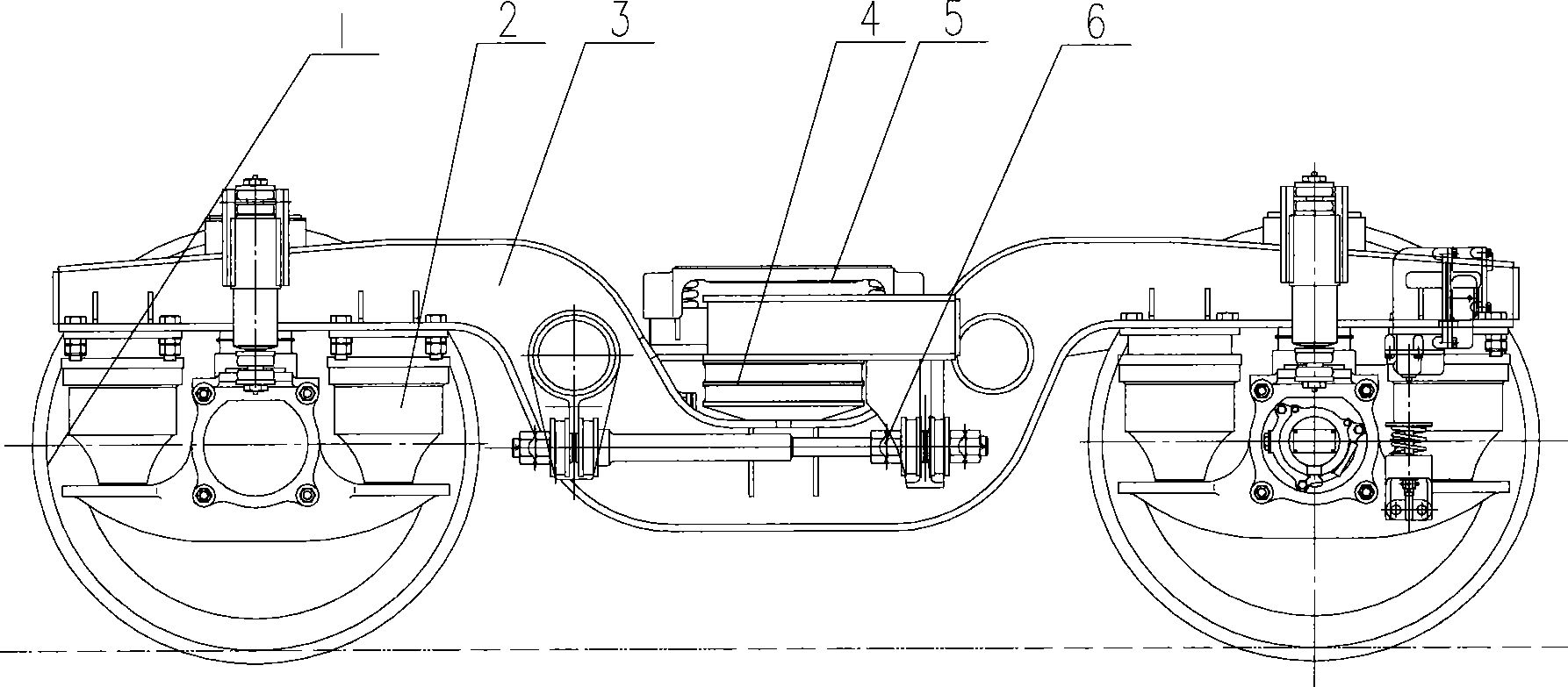
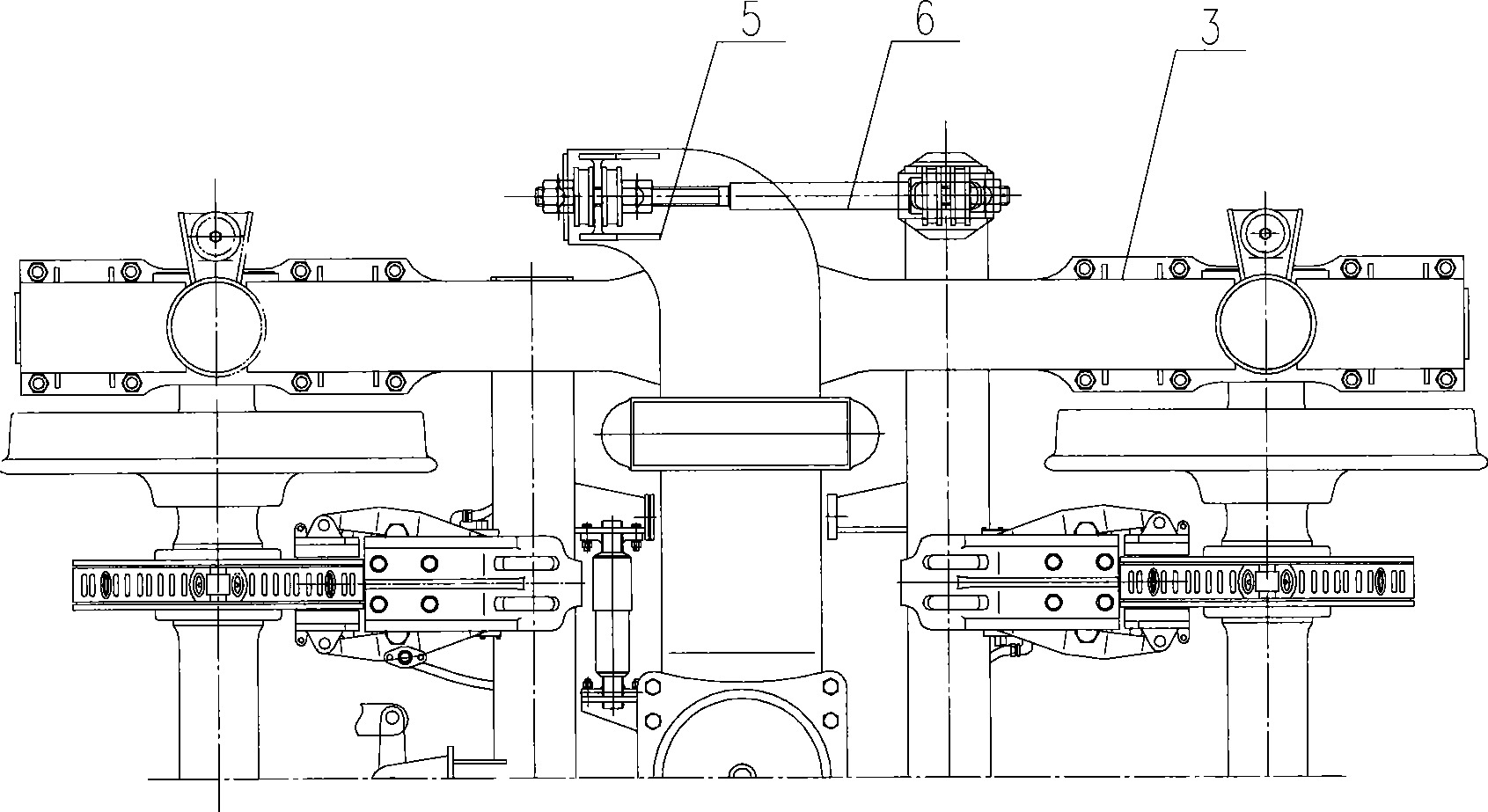
[0041] The present invention will be described in detail below in conjunction with the accompanying drawings. The description in this part is only exemplary and explanatory, and should not have any limiting effect on the protection scope of the present invention.

[0042] It should be noted that: In this part, while describing the bogie, the longitudinal traction device will be described, and the longitudinal traction device will not be described separately.

[0043] Such as Figure 4 with Figure 5 As shown, the bogie provided by the embodiment includes a wheel set 1 , a primary suspension system 2 , a frame 3 , a secondary central suspension system 4 , and a bolster 5 . The connection relationship of its various parts is the same as that of the prior art. The bolster 5 has a lower center plate matched with the truck box, and is installed in the middle of the frame 3 through the secondary central suspension system 4, and the frame 3 is installed in the middle of the frame 3 ...


PUM


Abstract

This invention discloses a longitudinal towing device and a bogie with the same. The longitudinal towing device is used for connecting a swing bolster and a framework of the bogie, and comprises a towing pull rod and two pull rod seats, wherein the two pull rod seats can be respectively fixed with the swing bolster and the framework, the towing pull rod is connected with the two pull rod seats through a spherical hinge assembly, and the spherical hinge assembly comprises a spherical hinge axle and a spherical hinge sleeve; the spherical hinge axle is articulated and matched with the spherical hinge sleeve through a spherical curved surface. Because the longitudinal towing device comprises spherical hinge assemblies, and the spherical hinge axle and the spherical hinge sleeve can be relatively rotated, on one hand, the longitudinal towing device can ensure to transmit larger longitudinal towing force, and on the other hand, the longitudinal towing device can ensure that the additional lateral stiffness of the bogie is smaller, enables the bogie with the longitudinal towing device to keep larger transverse natural bow while transmitting longitudinal towing force, and ensures the railway vehicle to have better dynamics performance.

Description

technical field [0001] The invention relates to a connection mechanism, in particular to a longitudinal traction device for a railway freight car bogie, and also to a bogie with the longitudinal traction device. Background technique [0002] The bogie is an important part of the railway vehicle, and the railway vehicle is supported on the railway track through the bogie; therefore, the performance of the bogie directly affects the safety and running performance of the railway vehicle. [0003] combine figure 1 with figure 2 As shown, currently, a truck bogie generally includes a wheel set 1 , a primary suspension system 2 , a frame 3 , a secondary central suspension system 4 , and a bolster 5 . The bolster 5 has a lower center plate matched with the truck box, and is installed in the middle of the frame 3 through the secondary central suspension system 4, and the frame 3 is installed on the wheel set 1 through the primary suspension system 2, and the wheel set 1 can be co...

Claims


Application Information

Patent Timeline
IPC IPC(8): B61G9/00B61F5/04B61F5/52
Inventor 徐世峰胡海滨邢书明吕可维
Owner CRRC QIQIHAR ROLLING CO LTD
Why Eureka
Try Eureka