Automatic edge sealing process for vacuum glass

A vacuum glass and glass technology, which is applied in glass forming, glass reshaping, glass manufacturing equipment, etc., can solve the problems that restrict the wide application of vacuum glass, affect the wide use of vacuum glass, hinder the development of vacuum glass, etc., and achieve self-extraction The effect of reliable air sealing, eliminating hidden dangers of air leakage, and improving the overall quality level

Inactive Publication Date: 2009-07-15
左树森
View PDF4 Cites 13 Cited by
  • Summary
  • Abstract
  • Description
  • Claims
  • Application Information

AI Technical Summary

Problems solved by technology

The disadvantages of this structure are: 1. The vacuuming time is too long, the work efficiency is low, and the exhaust pipe must be melted; 2. There will be a section of melted exhaust pipe on each vacuum chamber of the vacuum glass product. It is very unsightly and easy to break; 3. At least one exhaust pipe is left between adjacent glass, and each exhaust pipe has a hidden danger of air leakage, which is not convenient for handling and construction, resulting in an increase in the scrap rate; 4. The whole process is complicated , not easy to operate, high cost
The above-mentioned various defects have seriously affected the wide use of vacuum glass and hindered the further development of vacuum glass
[0003] To sum up, the existing vacuum glass manufacturing process is relatively complicated, the vacuuming time is too long and unreasonable, the production efficiency is low, the scrap rate is high, the production cost is high, and the sales price is high, which affects the production of vacuum glass and restricts Wide application of vacuum glass

Method used


Image

  • Automatic edge sealing process for vacuum glass
  • Automatic edge sealing process for vacuum glass
  • Automatic edge sealing process for vacuum glass

Examples


Embodiment 1

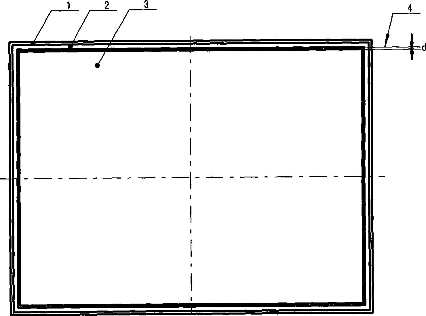
[0028] Example 1: see figure 1 , Figure 4 , Figure 5 , Image 6 .

[0029] An automatic vacuum glass edge sealing process, including setting a support on the base glass 1, placing the upper glass 3 on the base glass, sealing the edge with low-melting glass powder between the upper glass and the base glass, and putting it into a vacuum Heating in the heating furnace, taking out to obtain finished vacuum glass products. In this embodiment, in the step of edge sealing with low-melting-point glass frit between the top glass and the substrate glass, the top glass is placed on the substrate glass and leaves an edge on the substrate glass, and the low-melting-point glass powder strip or powder 2 Placed on the substrate glass and leave a gap 4(d) with the upper glass, the gap is used for escaping air; and after the low-melting point glass powder strip is melted in the heating furnace, the gap is fused by itself and passed through the The suction effect is sucked between the upp...

Embodiment 2

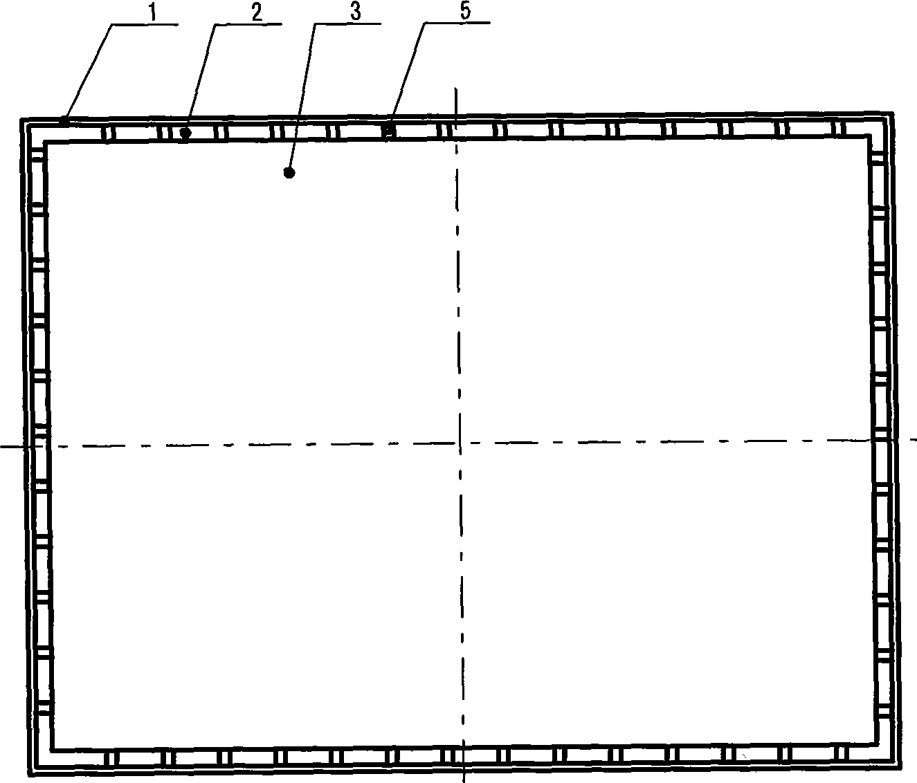
[0030] Example 2: see figure 2 , Figure 7 , Figure 8 , Figure 9 . In this embodiment, the same thing as Embodiment 1 is that the top glass is placed on the substrate glass, an edge is left on the substrate glass, and the low-melting point glass powder strip is placed on the substrate glass. The difference is: 1. The low-melting point glass powder strip is closely attached to the upper glass without leaving a gap; 2. The low-melting point glass powder strip is made like Figure 7 Represented semicircular groove 5, the semicircular groove communicates with the cavity formed between the upper glass and the substrate glass, or as Figure 8 Shown in the low-melting point glass powder type bar, be shaped on the circular through-hole 6 that communicates with the cavity formed between the upper sheet glass and the substrate glass; Figure 9 As shown, the low-melting point glass powder type bar is made into discontinuous section 7, and the discontinuous section is used to esca...

Embodiment 3

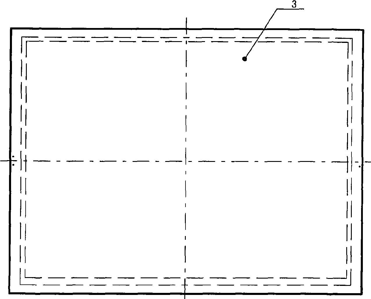
[0031] Embodiment 3: see image 3 , Figure 10 . In this embodiment, the edges of the top glass and the substrate glass are flush, and a downtilt is made on the top glass, and a low-melting point glass strip is placed between the downtilt position of the top glass and the substrate glass. The glass type strip can leave a gap as shown in embodiment 1, also can make gap on the low-melting point glass powder type strip as shown in embodiment 2, its function is identical with embodiment 1.

[0032] The above-mentioned glass powder strips can also be replaced by low-melting glass powder piles, which have basically the same effect and will not be repeated here.


PUM


Abstract

The invention relates to an automatic edge sealing technology for vacuum glass, which comprises the following steps of arranging supporters on basal board glass, arranging upper plate glass on the basal board glass, using low melting-point glass powder between the upper plate glass and the basal board glass for sealing edges, placing the upper plate glass and the basal board glass into a vacuum heating furnace to be heated and taking out upper plate glass and the basal board glass to get a finished vacuum glass, wherein in the step of using the low melting-point glass powder for sealing the edge, a section bar of low melting-point glass powder or the low melting-point glass powder is arranged on the basal board glass, and a gap of air escaping in the evacuation in the heating furnace is left in a chamber formed between the basal board glass and the upper plate glass. The invention has simple integrated structure, greatly shortens the evacuation time, increases the work efficiency, has reliable automatic evacuation and sealed package, good air tightness, little air leakage hazard, attractive appearance and production technology simplification, greatly promotes the development of the vacuum glass industry, and is particularly suitable for the industrialized, the scale and the standardized production of the vacuum glass.

Description

technical field [0001] The invention belongs to the field of vacuum glass, in particular to an automatic edge sealing process for vacuum glass. Background technique [0002] The sound insulation, heat insulation and thermal insulation properties of vacuum glass are much better than ordinary glass or laminated glass, and its application prospect is very broad. The traditional vacuum glass packaging method is to place a suction pipe between the edges of two adjacent layers of glass, use the suction pipe to connect the negative pressure generator to introduce negative pressure into each vacuum cavity, and then melt the suction pipe to carry out each suction port. of sealing. The disadvantages of this structure are: 1. The vacuuming time is too long, the work efficiency is low, and the exhaust pipe must be melted; 2. There will be a section of melted exhaust pipe on each vacuum chamber of the vacuum glass product. It is very unsightly and easy to break; 3. At least one exhaust...

Claims


Application Information

Patent Timeline
Patent Type & Authority Applications(China)
IPC IPC(8): C03B23/203C03B23/24
Inventor 左树森
Owner 左树森
Why Eureka
Try Eureka