
Gravity force balancing apparatus
A technology of gravity balance and cylinder, applied in the direction of balance weight, etc., can solve the problems of low response speed of hydraulic balance, low balance precision, and larger overall volume of machine tools, and achieve the effect of simple structure, good synchronization and easy implementation
- Summary
- Abstract
- Description
- Claims
- Application Information
AI Technical Summary
Problems solved by technology
Method used
Image

Examples
Embodiment Construction
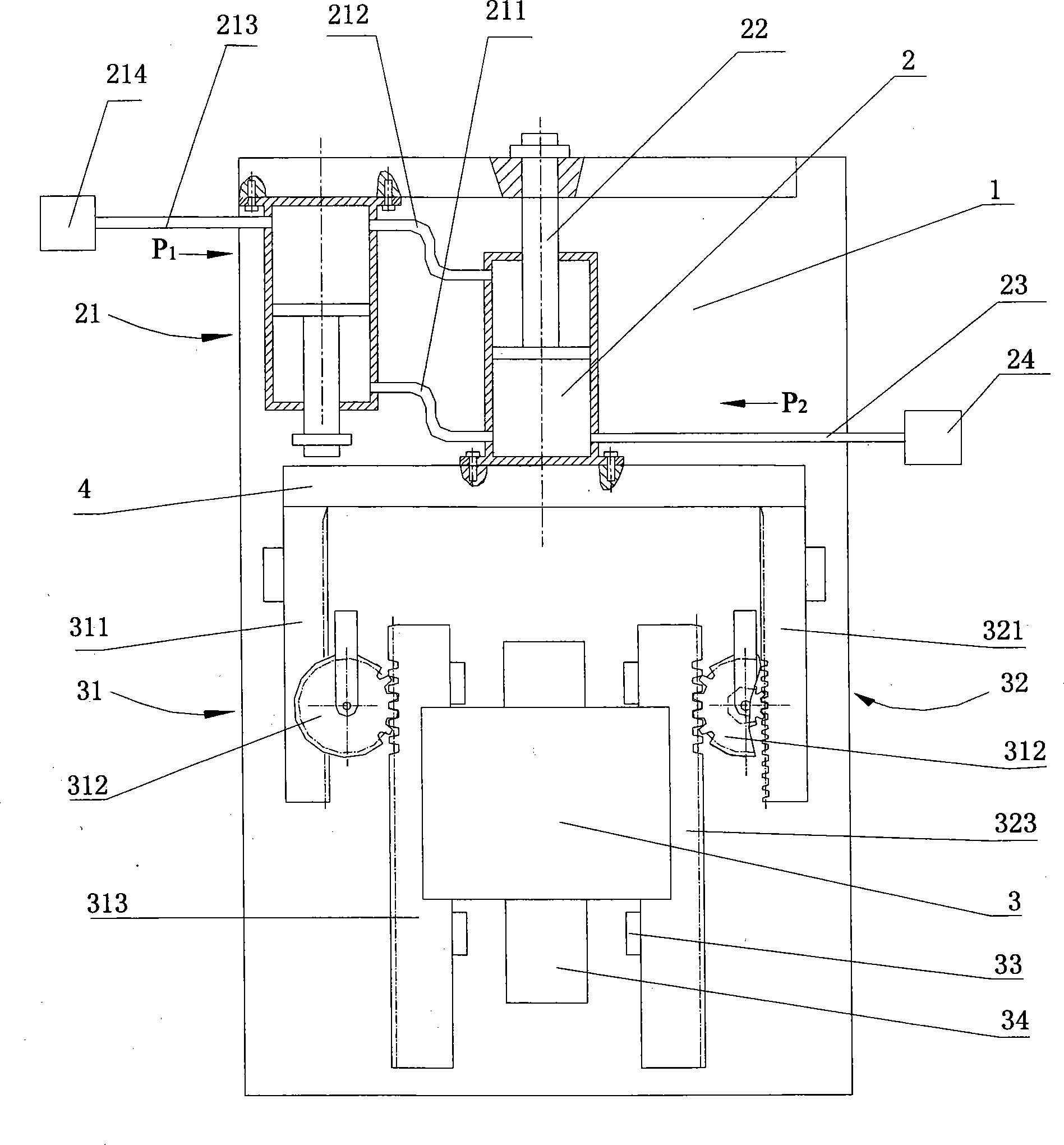
[0040] See attached figure 1 , The gravity balance device of this embodiment of the present invention uses cast iron to make the bracket 1 in the shape of H. The connecting piece 4 is made of steel with good rigidity and installed in the center of the bracket 1 in the shape of a beam. One side of the connecting piece 4 is fixedly connected to the first cylinder 2. The left side of the first cylinder 2 is pipe connected to the second cylinder 21. The specifications of the second cylinder 21 and the first cylinder 2 are the same, so the cross-sectional areas of the pistons of the two are the same, and the cross-sectional areas of the piston rods of the two are also the same, and the two are installed in parallel and oppositely. The cylinder base of the second cylinder 21 is directly fixed to the bracket 1; the outer end of the piston rod 22 of the first cylinder 2 is installed on the upper edge of the bracket 1. The rodless cavity of the second cylinder 21 and the rod cavity of the ...
PUM
 Abstract
Description
Claims
Application Information