Sea ice thickness measurement apparatus and method

A thickness measurement and height technology, applied in the direction of measuring devices, optical devices, instruments, etc., can solve the problems of limited observation accuracy and no commercial products of electromagnetic induction ice thickness detection equipment

Inactive Publication Date: 2009-07-15
POLAR RES INST OF CHINA
View PDF0 Cites 14 Cited by
  • Summary
  • Abstract
  • Description
  • Claims
  • Application Information

AI Technical Summary

Problems solved by technology

[0005] Underwater upward-looking sonar technology is a classic method of ice thickness observation. The upward-looking sonar equipment is mounted on a submarine or underwater robot platform to obtain sea ice thickness data, which is widely used by scientists. However, this technology The observation accuracy is limited by the position of the underwater transducer and the influence of changes in water temperature, tide and air pressure;
[0006] Electromagnetic induction technology, which has the advantages of non-contact and fast working speed, but there is no commercial product of electromagnetic induction ice thickness detection equipment so far

Method used


Image

  • Sea ice thickness measurement apparatus and method
  • Sea ice thickness measurement apparatus and method
  • Sea ice thickness measurement apparatus and method

Examples


Embodiment 1

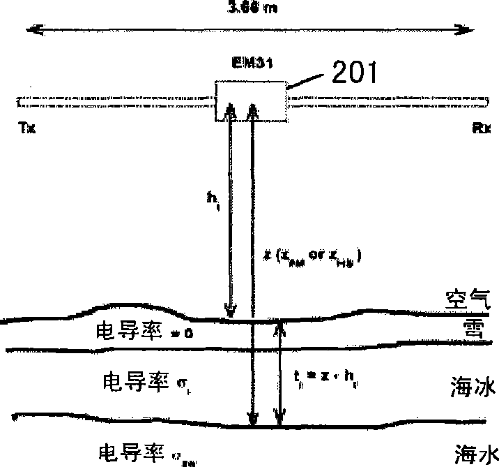
[0026] figure 2 One embodiment of the method of measuring sea ice thickness of the present invention is shown.

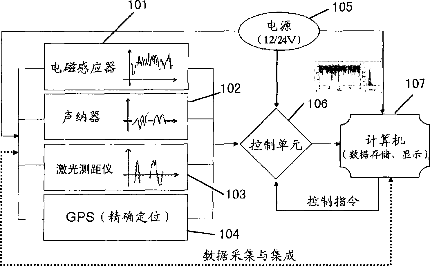
[0027] Such as figure 2 As shown, will figure 1 The shown sea ice thickness measuring device 201 is positioned above the sea ice. The electromagnetic sensor 101 emits and receives electromagnetic field signals perpendicular to the sea ice, and the sonar device 102 emits and receives sonar signals perpendicular to the sea ice. Wherein, the sonar 102 is used for measuring the accurate height of the device 201 from the ice surface, namely figure 2 The height h1 in; the electromagnetic inductor 101 is used to measure the height of the device 201 from the interface between sea ice and seawater based on the above-mentioned principle, that is figure 2 The height z in .

[0028] back to figure 1 , the data collected by the above-mentioned electromagnetic inductor 101 and sonar 102 will be transmitted to the control unit 103, and the control unit can calculate the ...

Embodiment 2

[0034] Figure 4 Another embodiment of the invention is shown, which relates to another method of measuring sea ice thickness. This method mainly uses figure 1 Sonar 102 and laser 103 are shown. According to this embodiment, the sea ice thickness measuring device 401 should at least include a sonar 102 and a laser 103 . go to Figure 4 , as in Embodiment 1, the sea ice thickness measuring device 401 of the present invention, that is, the sonar 102 and the laser 103, is fixed above the sea ice. In the same manner as in Embodiment 1, the height H1 of the seawater surface from the device 401 and the height H2 of the sea ice upper surface from the device 401 can be measured with the sonar 102 . At the same time, the laser 103 can also be used to measure the height H1 of the seawater surface from the device 401 and the height H2 of the sea ice surface from the device 401 in a similar manner, and the ice side height H can be obtained by calculating H1-H2. Then, using Archimedes...


PUM


Abstract

The invention provides a sea ice thickness measuring apparatus which comprises a body. The body comprises: a sonar device which transmits and receives sonar signal perpendicular to the seawater or sea ice; a laser which transmits and receives laser signal perpendicular to the seawater or sea ice; and a control unit which is in data connection with the sonar device and the laser; wherein, the control unit calculates the first height between the body and the sea ice upper surface according to the sonar signal and the laser signal, calculates the second height between the body and the seawater surface according to the sonar signal and the laser signal, and obtains the ice side height by subtracting the first height from the second height, then calculating the sea ice thickness by using the archimedes law. The invention further provides a sea ice thickness measuring method. The invention realizes the repeatable observation of large-scale sea ice, and can measure the sea ice thickness accurately.

Description

technical field [0001] The invention relates to the field of ocean monitoring, in particular to a novel method and device for measuring sea ice thickness. Background technique [0002] The thickness of sea ice and its variation is a frontier hotspot and technical difficulty in the field of global change research, and scientists from various countries are working hard to find technical methods to solve this problem. [0003] Sea ice thickness is particularly significant and sensitive to the coupling process of atmosphere-sea ice-ocean, and directly determines the exchange process and rate of sea-air energy and matter; dominates the thermodynamic and dynamic characteristics of sea ice, and affects the movement of sea ice , deformation and freezing and ablation process. At present, the following centralized sea ice thickness monitoring technologies mainly exist: [0004] Satellite remote sensing technology. With the rapid development of satellite technology and spaceborne sen...

Claims


Application Information

Patent Timeline
Patent Type & Authority Applications(China)
IPC IPC(8): G01B17/02G01B11/06
Inventor 孙波郭井学李娜李丙瑞李群唐学远
Owner POLAR RES INST OF CHINA
Why Eureka
Try Eureka