Miniature microwave sampler

A sampler and microwave technology, applied in waveguide devices, impedance networks, digital technology networks, etc., can solve problems such as inability to effectively reduce circuit size and large layout area

Inactive Publication Date: 2009-07-15
FINETEK CO LTD
View PDF0 Cites 6 Cited by
  • Summary
  • Abstract
  • Description
  • Claims
  • Application Information

AI Technical Summary

Problems solved by technology

However, the microwave sampler (70) cannot effectively reduce the size of the microwave sampler (70) due to the large area of ​​the layou

Method used


Image

  • Miniature microwave sampler
  • Miniature microwave sampler
  • Miniature microwave sampler

Examples


Embodiment Construction

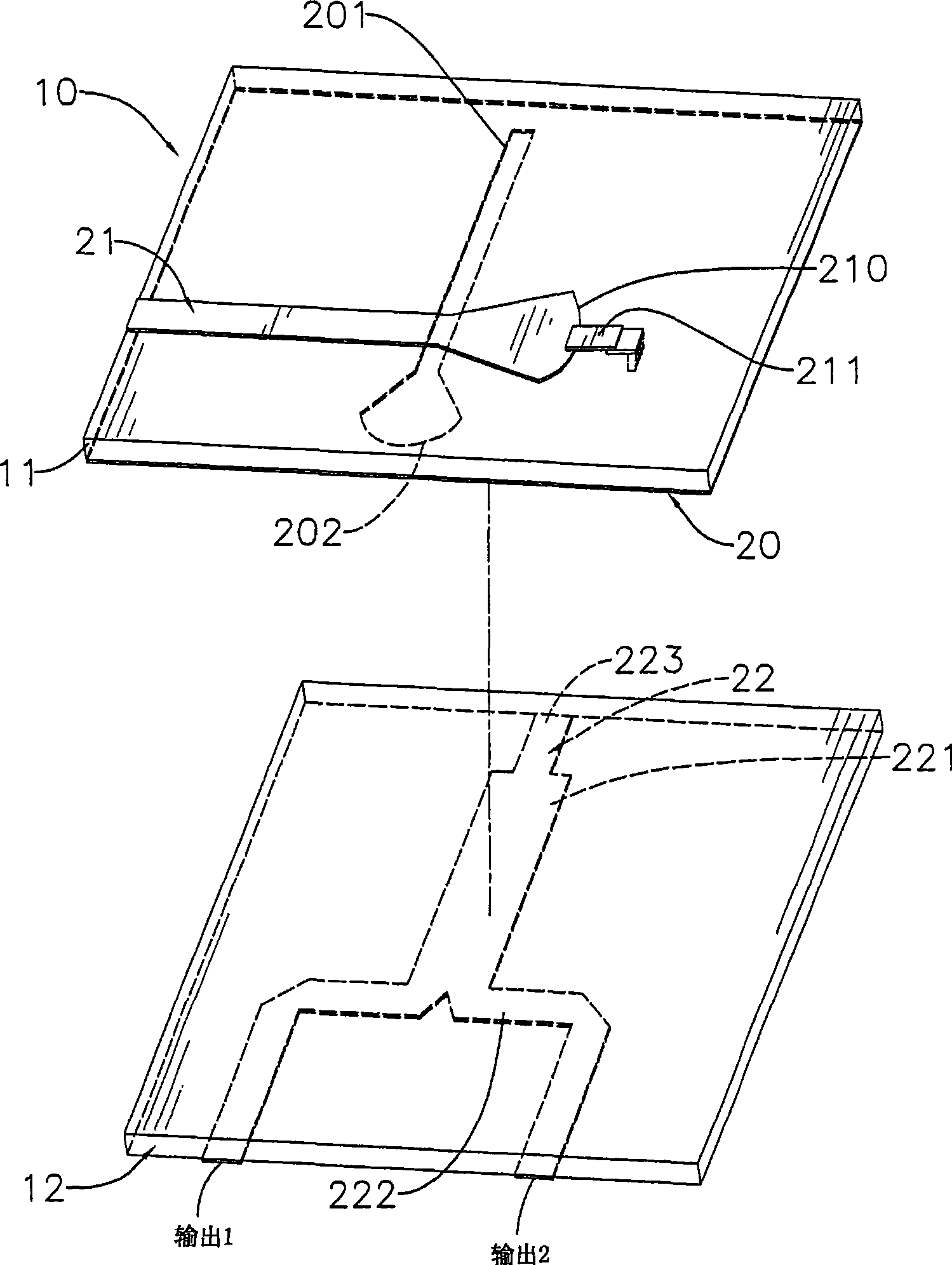
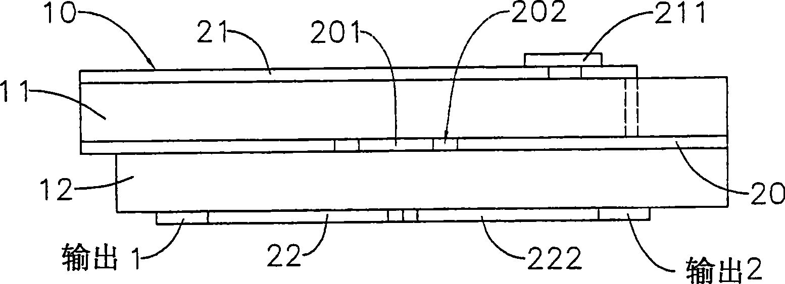
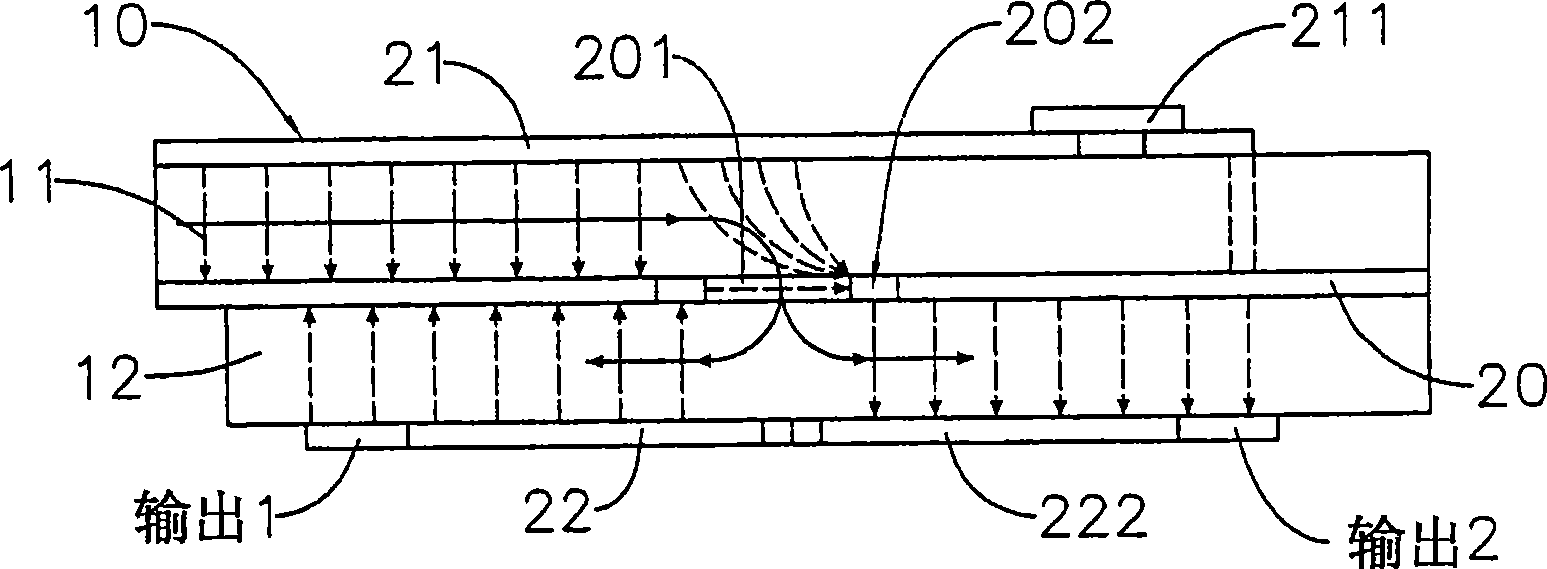
[0036] For a preferred embodiment of the present invention, please refer to figure 1 , figure 2 As shown, it is mainly to construct at least one magic T (Magic T) circuit on a substrate (10), and the substrate (10) is laminated by a first base material (11) and a second base material (12) Composition, the overlapping surface of the first base material (11) and the second base material (12) is formed with a fully covered grounding layer (20), in this embodiment, the grounding layer (13) is formed on the first On the bottom surface of the substrate (11); the magic T circuit constructed on the aforementioned first and second substrates (11) (12) again includes:

[0037] An aperture line (201) is formed on the aforementioned ground layer (20). In this embodiment, the first substrate (11) forming the ground layer (20) is rectangular, and the aperture line (201 ) is narrow and long, and it is located in the center of the first base material (11), and its long side is parallel to...


PUM


Abstract

The invention provides a miniaturized microwave sampler, mainly composed of a ground plane on an overlapping plane of a first substrate and a second substrate and a slot-hole line formed on the ground plane; a first microstrip line formed on the surface of the first substrate and one end of the microstrip line being the input terminal of the local pulse signal; a T-shaped second microstrip line formed on the bottom of the second substrate and one end of the second microstrip line being the input terminal of the RF signal and another end of fork shape being in right-angle cross with the first microstrip and constituting a electromagnetic field coupling by the slot-hole line on the ground plane; a Magic T circuit capable of effectively reducing the size of the miniaturized microwave sampler and increasing the efficiency of the sampling signal.

Description

technical field [0001] The invention relates to a microwave sampler, in particular to a miniaturized microwave sampler using ultra-wideband (UWB) communication and Time Domain Reflectance (TDR) measurement system. Background technique [0002] In the application of UWB communication system and TDR measurement system, the microwave sampler is an important component of the system receiving end. However, due to the large overall circuit size of known microwave samplers, there is still considerable room for improvement in volume reduction: [0003] like Figure 8 Disclosed is a block diagram of a receiving end sampling module of a UWB communication system, including a microwave sampler (70) and a digital signal processing circuit (80), and the digital signal processing circuit (80) is roughly composed of an A / D converter ( 81), a filter (82) and a baseband processor (83). As for the microwave sampler (70), a balance structure or a ring structure is generally used. Among them,...

Claims


Application Information

Patent Timeline
IPC IPC(8): G01R29/08H03H17/00H01P1/38H01P5/02H01Q13/08
Inventor 马自庄周金锋
Owner FINETEK CO LTD
Why Eureka
Try Eureka