External push broach

A technology of pushing and pulling knives and pressure plates, which is applied in the direction of broaching knives, broaching machines, gear teeth, etc., can solve the problems that the cutting consistency of circular blade teeth cannot be guaranteed, the knife rack cannot be repaired and used, and the position accuracy is difficult to guarantee, so as to achieve saving Processing machine tools and equipment, the cost is beneficial to environmental protection, and the effect of high processing precision

Inactive Publication Date: 2009-07-22
杨方洲
View PDF2 Cites 5 Cited by
  • Summary
  • Abstract
  • Description
  • Claims
  • Application Information

AI Technical Summary

Problems solved by technology

[0004] 1. It is difficult to process the blade teeth, difficult to assemble, and the precision of the tool is low
The cutting part of the outer broach is composed of a combination of slender blades and racks. The slender blades have poor rigidity and are difficult to process; the cutting consistency of the circular blade teeth cannot be guaranteed during cutting; the position accuracy during installation is also difficult to guarantee, which makes The overall accuracy of the tool is low
[0005] 2. The tool has low strength and is easy to chip
Since the cutting part is formed by connecting the installation cylinder and the inner cutting tooth, and includes two components in the circumferential direction, it is difficult to withstand large circumferential cutting stress, making the overall strength of the tool low and easy to chip
[0006] 3. High cost and inconvenient maintenance
When a specific tooth is damaged, the entire tooth rack needs to be replaced, so its maintenance is inconvenient and the maintenance cost is high. At the same time, the replaced tooth rack cannot be repaired and utilized

Method used


Image

  • External push broach
  • External push broach
  • External push broach

Examples


Embodiment Construction

[0030] The present invention is mainly used for the processing and molding of columnar body parts, especially gear parts. Since the structural principle of the present invention is designed for all columnar body structure parts, its processing principle is completely consistent for all columnar body structure parts, so this implementation The method only takes the gear as an example, and the technical solution of the present invention will be described in detail below in conjunction with the accompanying drawings.

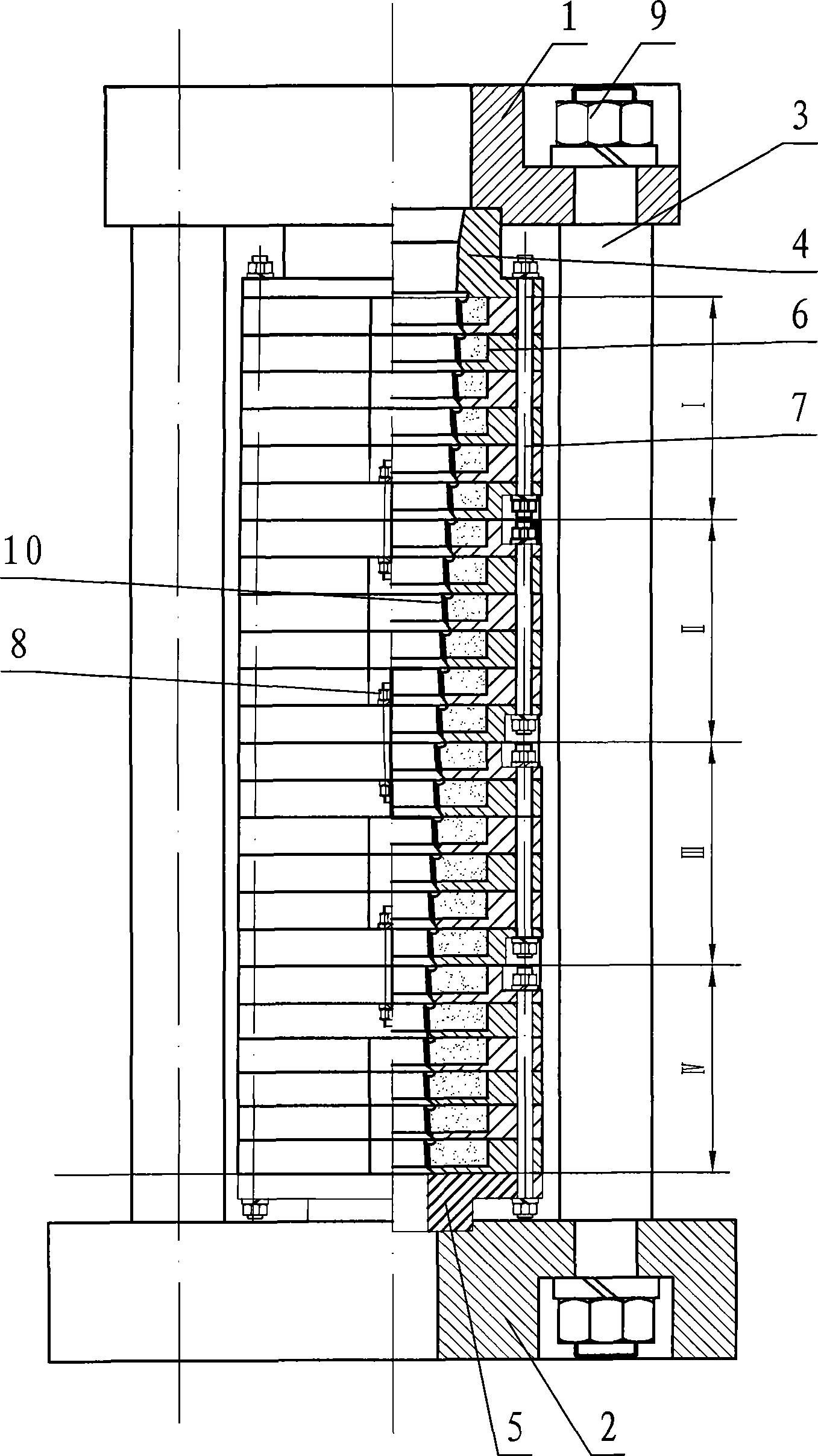
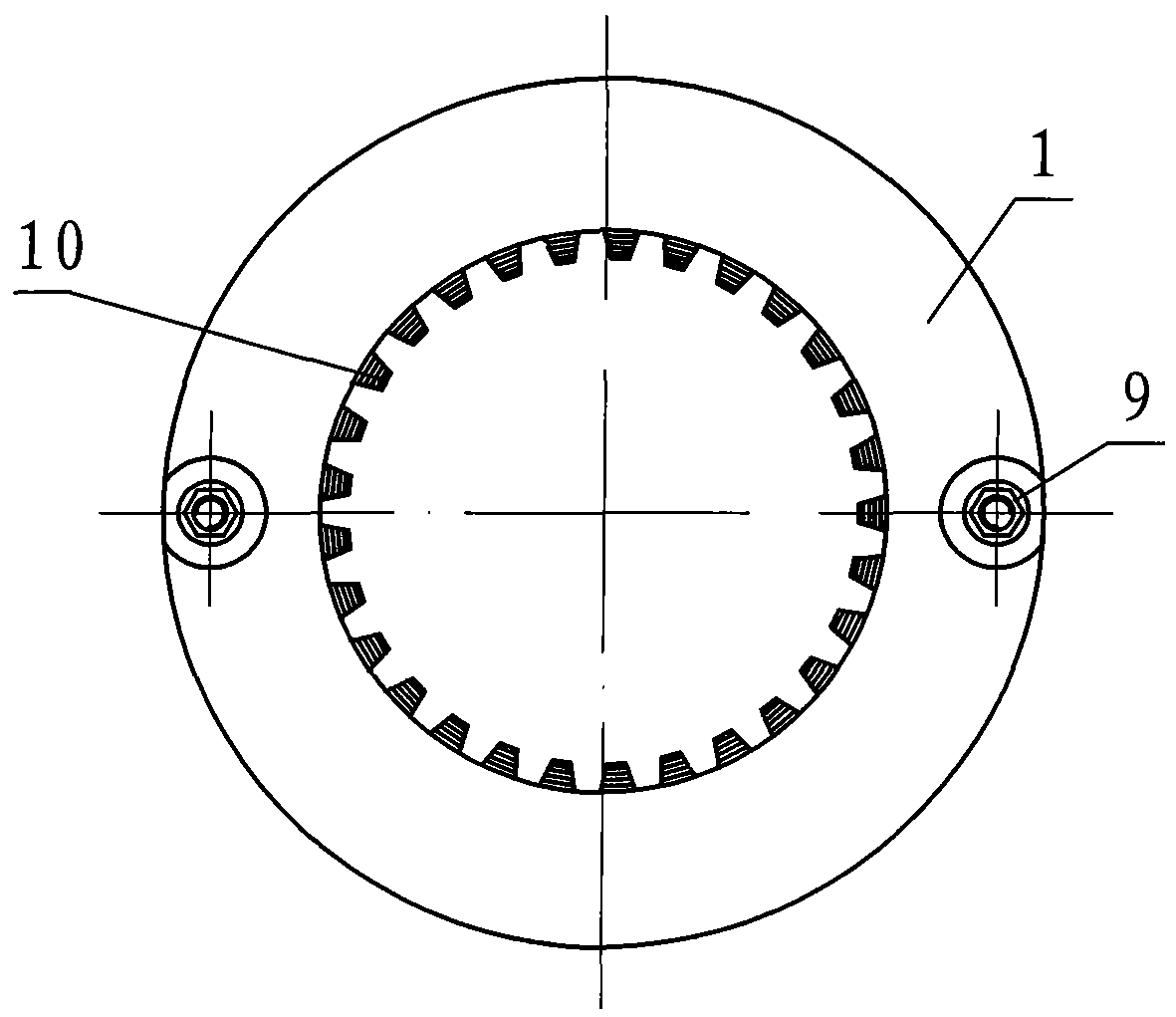
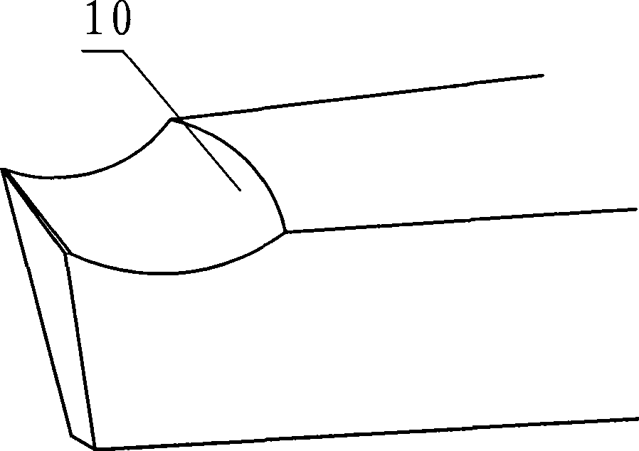
[0031] Such as figure 1 As shown, a push-out broach in this embodiment includes a front guide platen 1, a rear guide platen 2, and a connecting rod 3 connecting the two, and is crimped on the front guide platen 1 and the rear guide platen 2. The cutting part between them, wherein the cutting part is composed of initial cutting tooth part I, transition tooth part II, finishing tooth part III and correction tooth part IV, and each part is composed of a plurality of r...


PUM


Abstract

The invention discloses an external push-and-pull cutter for machining the shape of a columnar part. The cutter comprises a front guide platen, a rear guide platen, a connecting rod and a cutting part compression jointed between the front guide platen and the rear guide platen; the cutting part is formed by vertically superposing a plurality of annular inner tooth cutting blades of mold cavities with different dimension; the annular inner tooth cutting blade is provided with a plurality of inner cutting blade teeth which are wholly matched with the shape of a gear; the inner cutting blade teeth are in a ladder arrangement axially; and the annular inner tooth cutting blades are fixedly connected by positioning pins. The external push-and-pull cutter has the advantages of high production efficiency, energy conservation, raw materials conservation, equipment conservation, environmental protection, low cost, and the like, and has the characteristics of easy machining of blade teeth, simple structure, convenient assembly, low processing cost, high machining precision, high strength of the whole cutter, convenient maintenance, low maintenance cost, long service life, and the like.

Description

technical field [0001] The invention relates to a tool for machining the shape of a columnar part, in particular to an external broach for machining gears and cylindrical parts similar to gears. Background technique [0002] When processing cylindrical parts, it is usually processed by external cutting with ordinary tools, which has the disadvantages of complex processing procedures, a large number of supporting equipment, and high processing costs. Especially in gear processing, the traditional methods are forming method and generating method. When using these two methods to process gears, it is produced by hobbing (or shaping) + shaving + honing (or grinding). A large number of processing machine tools are required, which has low production efficiency, high energy consumption, large waste of raw materials, and poor environmental protection. There are gear base pitch differences and pitch accumulation errors during gear processing. Large, the extrusion deformation is serio...

Claims


Application Information

Patent Timeline
Patent Type & Authority Applications(China)
IPC IPC(8): B23D43/02B23D43/04B23F21/26
Inventor 杨方洲
Owner 杨方洲
Why Eureka
Try Eureka