
Earth-steel combined cofferdam construction method for underwater pile cap of bridge

A technology of water bearing platform and construction method, which is applied in the direction of basic structure engineering, construction, caisson, etc., can solve the problems of high difficulty in quality control, long construction period, large investment in temporary structures, etc., and achieves easy quality control, shortened construction period, The effect of less consumption of steel and concrete

Active Publication Date: 2009-07-22
ROAD & BRIDGE INT
View PDF0 Cites 8 Cited by
  • Summary
  • Abstract
  • Description
  • Claims
  • Application Information

AI Technical Summary

Problems solved by technology

This method can not only expand the scope of application of geotechnical cofferdams, but also solve the problems of long construction period, large investment in temporary structures, and high difficulty in quality control by using only steel (concrete) casings.

Method used


Image

  • Earth-steel combined cofferdam construction method for underwater pile cap of bridge
  • Earth-steel combined cofferdam construction method for underwater pile cap of bridge
  • Earth-steel combined cofferdam construction method for underwater pile cap of bridge

Examples


Embodiment 1

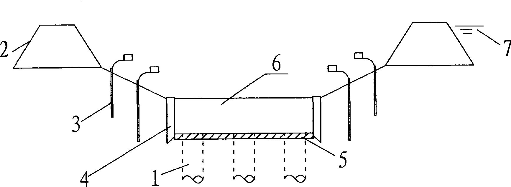
[0023] The size of the main pier cap of a bridge is 25.6×22.5×5.5m, the bottom elevation of the platform is -6.5m, the riverbed elevation is +1.0m, the normal water level elevation is +4.5m, and the tide height is 0.5m. The riverbed soil is a silt layer. Construction of soil-steel cofferdam, see attached image 3 . The specific technical solution is as follows.

[0024] (1) First design the geotechnical cofferdam and steel box according to the construction environment

[0025] ① In order to better resist the external water pressure, the geotechnical cofferdam is designed into an elliptical shape, with a long diameter of 43m and a short diameter of 40m on the centerline of the geotechnical cofferdam. The cross section is designed as a trapezoidal section, with a bottom width of 20m, a top width of 12m, and a height of 4m. It is constructed in 8 layers and formed by sand blowing.

[0026] ②The steel box is a double-wall structure, the inner wall is the same as the shape of the platfo...

Embodiment 2

[0053] The following uses another example to compare the effects of the steel (concrete) box construction method and the soil-steel (concrete) combined cofferdam construction method for the same cap. Table 2 is a table of various parameters of Comparative Example 2.

[0054]

[0055] Table 2: Various parameter tables of Comparative Example 2

[0056] For the above example 2, the steel box method is adopted for construction. The size of the steel box box is 15m in height×96.2m in circumference×1.2m in thickness, and the thickness of the sealed bottom concrete is 2m; The box size is 4m high x 96.2m perimeter x 1.2m thick, the base cushion concrete thickness is 0.7m, the perimeter of the soil cofferdam is 160m, and the height is 5m. Table 3 compares the effects from the aspects of construction period, raw material saving, quality control, and construction investment.

[0057]

[0058] Table 3: Comparison of effects of soil-steel cofferdam method and steel box method for purchase ...


PUM


Abstract

A soil-steel combined cofferdam construction method used for a bridge under-water bearing platform includes the following steps: a geotechnical cofferdam is constructed around the bearing platform to be constructed after the pile foundation is completed; a mud pump is adopted to pump the water out from the cofferdam and a well-point dewatering device is arranged and operated inside the cofferdam according to the construction proposal after the geotechnical cofferdam is completed; the completed telescopic caissons are combined at the bridge site and a soil-cleaning device is adopted to taking the soil from the telescopic caissons; the telescopic caissons are sunk and after the telescopic caissons sinks to the designed position the concrete construction for the base cushion is carried out; and the construction for the platform steel reinforcement and concrete is carried out after the intensity of the base cushion concrete meets the requirement.

Description

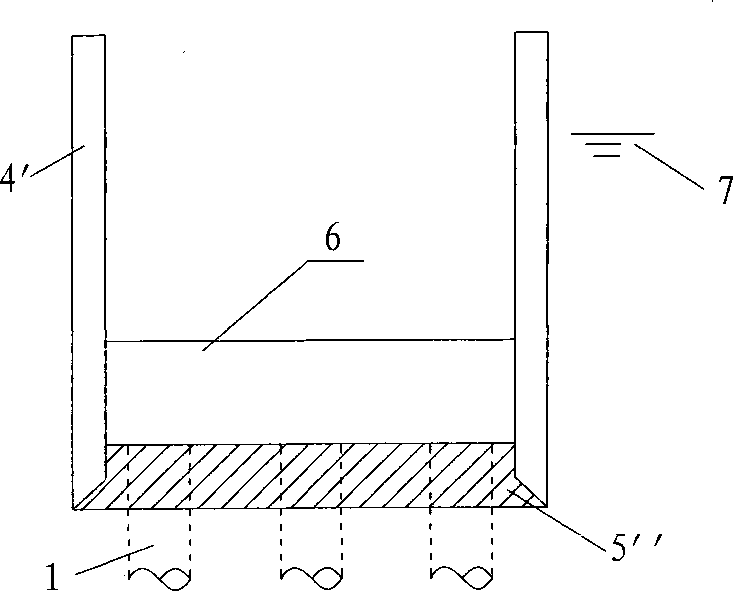
Technical field [0001] The invention relates to a construction method of a bridge in the water bearing platform, which belongs to the field of bridge construction. Background technique [0002] At present, the construction of bridge caps in water is based on different hydrological conditions. Steel (concrete) boxes and geotechnical cofferdams are usually used. One common point of these methods is to isolate the construction area of ​​caps from the outside water through temporary construction structures to isolate the construction area The water inside is drained, transforming the underwater construction of the platform into land construction. [0003] The main temporary construction structure in the usual steel (concrete) box construction is the steel (concrete) box and sealed concrete, see attached figure 1 . Its principle is to use the steel (concrete) box 4'and the back cover concrete 5” to isolate the external water 7, and then drain the water in the box to form a dry workin...

Claims


Application Information

Patent Timeline
Patent Type & Authority Applications(China)
IPC IPC(8): E02D19/04E02D23/00
Inventor 李德钦唐世连鲜正洪杨卫平肖向荣
Owner ROAD & BRIDGE INT
Learn More