Self-sealing quick-changing joint and its mounting method

An installation method and technology of internal joints, applied in couplings, metal rolling, metal rolling stands, etc., can solve problems such as low efficiency and leakage

Inactive Publication Date: 2009-07-22
CISDI ENG CO LTD
View PDF0 Cites 0 Cited by
  • Summary
  • Abstract
  • Description
  • Claims
  • Application Information

AI Technical Summary

Problems solved by technology

Solve the problems of inefficiency and leakage in the connection and switching between the pipeline on th

Method used


Image

  • Self-sealing quick-changing joint and its mounting method
  • Self-sealing quick-changing joint and its mounting method
  • Self-sealing quick-changing joint and its mounting method

Examples


Embodiment Construction

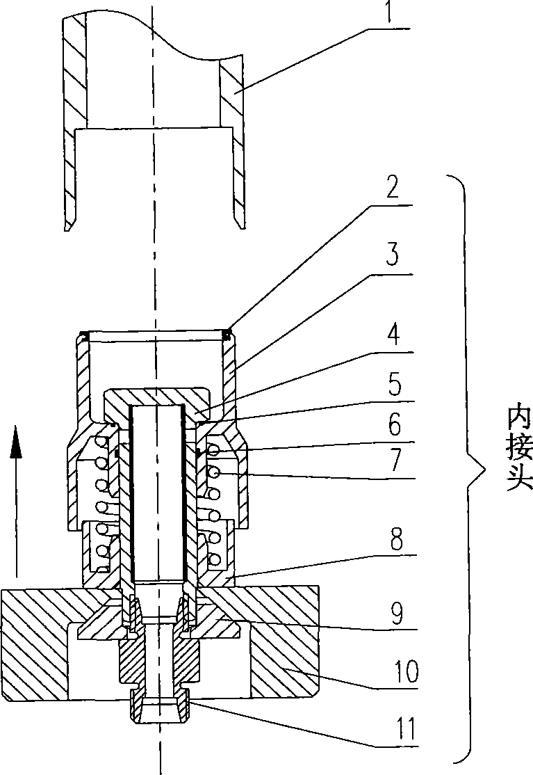
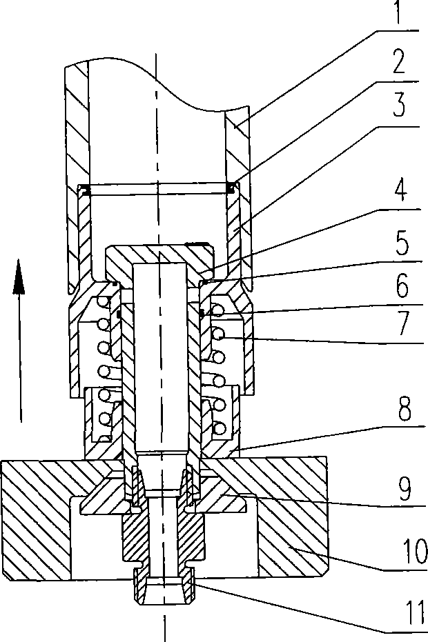
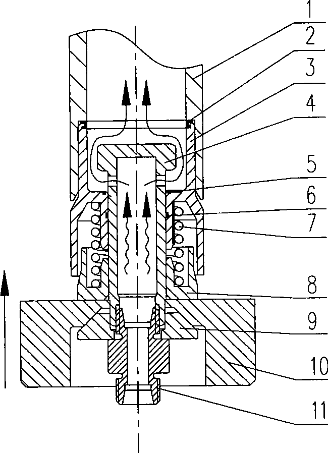
[0011] combined with figure 1 ~5 further illustrate the present invention:

[0012] The present invention mainly includes an independent outer tube 1 and an inner joint; the inner joint is mainly composed of a sealing ring (1) 2, an inner tube 3, a main pipe 4, a sealing ring (2) 5, a sealing ring (3) 6, a spring 7, and a ferrule 8. The positioning ring 9, the connecting plate 10 and the pipe joint 11 are composed of: a sealing ring (1) 2 is installed at the end of the inner pipe 3, and the spring 7 is set on the main pipe 4, and a sealing ring is installed between the upper surface and the end face of the main pipe 4 ( 2) 5, the sealing ring (3) 6 is installed between the inner ring and the outer cylindrical surface of the main pipe 4; The lower end is provided with a shaft shoulder and an internal thread, and after positioning by the positioning ring 9, the external thread of the pipe joint 11 is connected with the internal thread of the main pipe 4.

[0013] Under the act...


PUM


Abstract

The invention belongs to the mechanical engineering technical field, relating to a self-sealing quick change coupler and an installation method. An outer tube of the self-sealing quick change coupler is connected with a spigot by a sealing ring of the spigot. The end part of an inner tube of the spigot is provided with the sealing ring which is sheathed on a main pipe by a spring. The sealing ring is arranged between the upper surface of the spigot and the end surface of the shoulder of the outer ring at the upper part of the main part. The ring seal is arranged between the inner ring and the cylinder surface of the main pipe. The lower end of the spring is arranged in an internal groove of a cutting sleeve which is fixedly connected with a connection plate. The lower end of the main pipe is connected with a retaining ring and a tube union. The intercommunication and switching of the self-sealing quick change coupler is finished in the condition of sealing all the time, thus being capability of effectively preventing the leakiness of a system medium; the manual operation is not needed, thus effectively increasing the replacing efficiency of devices such as rolling mills and the like. The invention can be widely applied to the quick intercommunication and switching of pipelines and system pipelines on the devices needing quick change such as rolling mills, etc.

Description

technical field [0001] The invention belongs to the technical field of mechanical engineering, and relates to a self-sealing quick-change joint and an installation method. Background technique: [0002] In equipment such as rolling mills, due to production requirements, the equipment needs to be replaced frequently. The installation process is generally: first hoist the rolling mill slide on the slide rail, then connect the flat head of the hydraulic cylinder with the rolling mill slide, and then pass the hydraulic cylinder Move the mill to the rolling position, the replacement process is the reverse of the installation. Therefore, the pipelines on the equipment, such as oil and gas, cooling water, etc., and the system pipelines also need to be connected and switched frequently. For this reason, the general method is to use hose-connected joints. When the equipment is replaced, the pipeline is cut off manually, and then the equipment is replaced. When the new equipment is i...

Claims


Application Information

Patent Timeline
IPC IPC(8): F16L37/02B21B31/00
Inventor 陈莹卷李图学李传宣
Owner CISDI ENG CO LTD
Why Eureka
Try Eureka