Al technical title is built by PatSnap Al team. It summarizes the technical point description of the patent document.
A technology of motor and magnetic wheel, which is applied in the direction of magnetic circuit rotating parts, electric components, electromechanical devices, etc.
Inactive Publication Date: 2012-04-04
孙宗德
View PDF5 Cites 0 Cited by
Summary
Abstract
Description
Claims
Application Information
AI Technical Summary
This helps you quickly interpret patents by identifying the three key elements:
Problems solved by technology
Method used
Benefits of technology
Problems solved by technology
Various magnetic motors in the research stage all have shortcomings such as small force arm and dead point in work. The present invention overcomes the above-mentioned shortcomings, and fully utilizes the energy-saving and environmentally friendly new power machinery of electromagnetic energy-multi-magnetic wheel motor
Method used
Image
Click on the blue label to locate the original text in one second.
Reading with bidirectional positioning of images and text.
Examples
Embodiment Construction
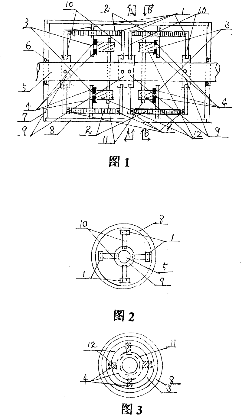
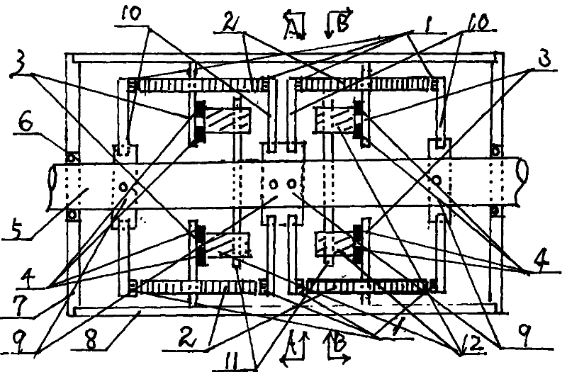
[0025] The shell (8) and the end cover (7) of the multi-magnetic wheel motor adopt cast iron casting molding, meet the requirements through machine tool processing and use when assembling. The straight shaft (5) and the spoke wheel (9) are made of cast steel and then machined to meet the size and precision requirements, then the spoke wheel (9) is assembled to the designated position of the straight shaft (5); a stainless steel tube with a suitable diameter is selected Cut to the required size, insert one end into the spoke (10) stub of the spoke wheel (9), rotate the steel pipe so that the plane at the end of the steel pipe forms a certain angle with the spoke surface, and then place the steel pipe and the spoke (10) stub fixed. The permanent magnet seat processed by the magnetic isolation material is fixed on the slope at the end of the spoke (10) together with the permanent magnet. Make the electromagnet seat (3) with insulating material and fix the electromagnet on this s...
PUM
Abstract
The invention relates to an engine provided with a plurality of magnet-wheels, which consists of a permanent magnet (1), an electromagnet (2), an electromagnet seat (3), an electric conduction copper ring (4), a straight shaft (5), a bearing (6), an end cover (7), a shell (8), a spoked wheel (9), a spoke (10), a carbon brush holder (11) and a carbon brush (12), and has the advantages of light weight, simple structure, no tail gas emission, energy conservation, etc. The engine combines part of the technology of a steam turbine with magnetic force, and has the advantages of large arm of force and moment as well as no dead center. By properly selecting the number of the spoked wheels (9) and the number of each line of spokes (10), the area of a magnetic pole, the intensity of a magnetic field and the length of the spoke (10) are properly chosen, and the engine having the required power can be designed, thus making contribution to opening up new power source. The principle of the action of the engine is that repulsion force is generated between the like magnetic poles which are the permanent magnet (1) and the electromagnet (2), component force which is vertical to the radial direction of the spoke is generated when the repulsion force is transmitted to the inclined plane at the end of the spoke (10) used for fixing the permanent magnet (1), and moment is formed; while, the same moment with opposite direction is generated by another spoke (10) which is symmetrical with the spoke (10) along the radial direction; the two moments form torque force to lead the straight shaft (5) to rotate.
Description
technical field [0001] The technical invention relates to a prime mover engine. Background technique [0002] At present, all kinds of prime movers are basically gasoline engines, diesel engines, steam turbines, water turbines, gas turbines and electric motors, etc. The most widely used are gasoline engines, diesel engines and electric motors, and most of the electric energy is thermal power, all of which have carbon dioxide emissions. Especially the oil crisis has restricted the economy. Development; forcing people with lofty ideals to find a clean and cheap alternative energy. The application of magnetic energy will open up a new path for this. The various magnetic motors in the research stage all have the disadvantages of small force arm and dead point in work. The present invention overcomes the above disadvantages and fully utilizes the energy-saving and environmentally friendly new power machinery of electromagnetic energy-multi-magnet wheel motor. Contents of th...
Claims
Application Information
Patent Timeline
Application Date:The date an application was filed.
Publication Date:The date a patent or application was officially published.
First Publication Date:The earliest publication date of a patent with the same application number.
Issue Date:Publication date of the patent grant document.
PCT Entry Date:The Entry date of PCT National Phase.
Estimated Expiry Date:The statutory expiry date of a patent right according to the Patent Law, and it is the longest term of protection that the patent right can achieve without the termination of the patent right due to other reasons(Term extension factor has been taken into account ).
Invalid Date:Actual expiry date is based on effective date or publication date of legal transaction data of invalid patent.