Voltage multiplying synchronous rectifying multi-resonance soft switching converter

A technology of synchronous rectification and synchronous rectifier tube, applied in the direction of converting DC power input to DC power output, AC power input converting to DC power output, instruments, etc. The effect of reducing conduction loss, reducing rms value, and simple driving

Active Publication Date: 2009-07-22
INVENTRONICS HANGZHOU
View PDF0 Cites 20 Cited by
  • Summary
  • Abstract
  • Description
  • Claims
  • Application Information

AI Technical Summary

Problems solved by technology

[0004] Disadvantages of LLC converter: Since LLC has the best working efficiency only near the resonant frequency, the rated operating point is often set near the resonant efficiency point. Large gain; when the input voltage increases or the output voltage decreases, a lower g

Method used


Image

  • Voltage multiplying synchronous rectifying multi-resonance soft switching converter
  • Voltage multiplying synchronous rectifying multi-resonance soft switching converter
  • Voltage multiplying synchronous rectifying multi-resonance soft switching converter

Examples


Example Embodiment

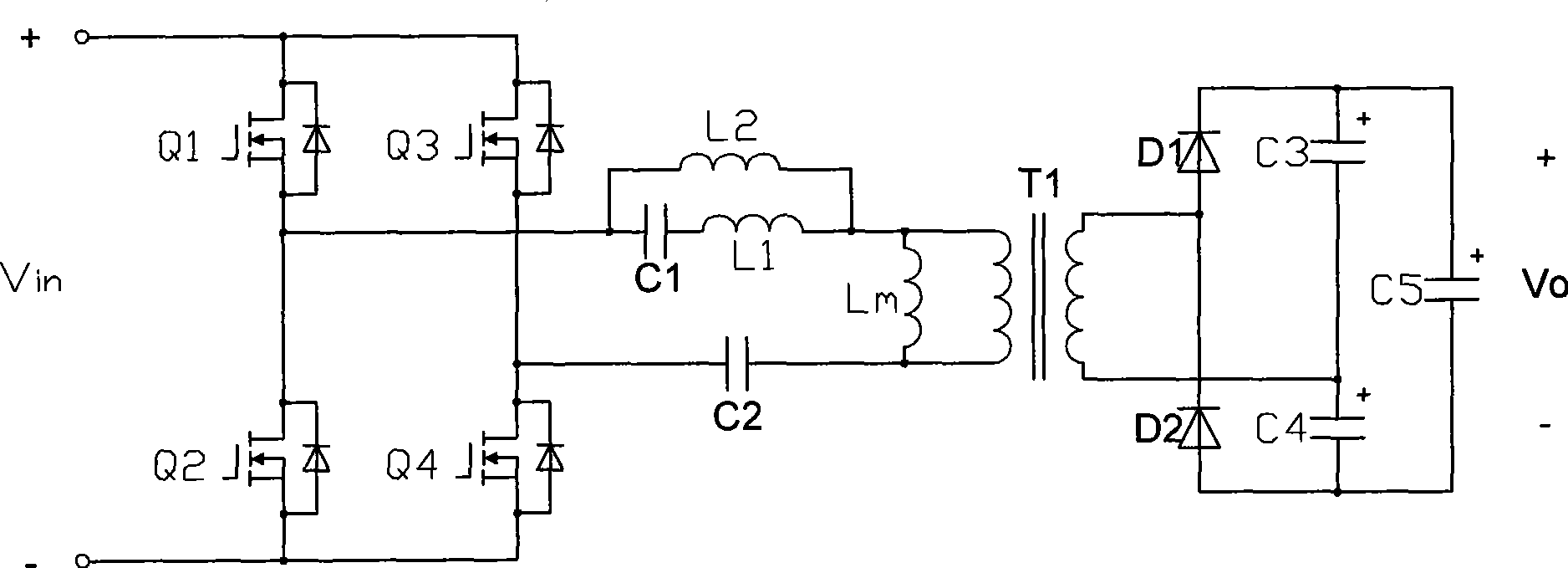
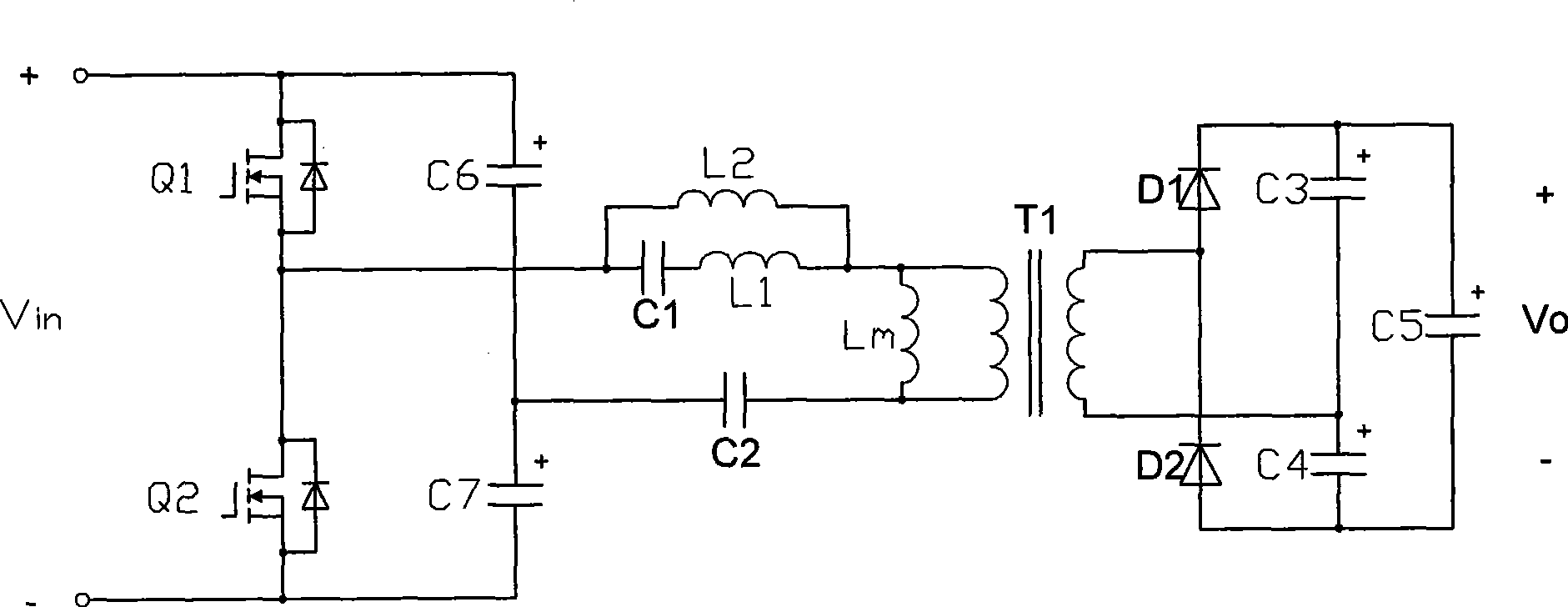
[0041] The resonant converter in specific embodiment 1 is as figure 2 As shown, it includes a resonant inductor L1, a resonant capacitor Cp1, an excitation inductance Lm, an auxiliary inductor L2, and an auxiliary capacitor Cp2; image 3 , Figure 4 It is a conversion circuit that adjusts the position of the resonant unit based on the impedance equivalent method.

[0042] The resonant impedance of the series resonant unit formed by L1, Cp1, L2 and Cp2 is:

[0043] Z ( s ) = s 4 · ( L 1 · Cp 1 · L 2 · Cp 2 ) + s 2 ...


PUM


Abstract

The invention discloses a voltage doubling synchronous rectification multi-resonance soft switch converter circuit which comprises a resonant inductance L1, a resonant capacitance Cp1, an excitation inductance Lm, an auxiliary inductance L2, an auxiliary capacitance Cp2, current transformators CT1 and CT2 as well as synchronous rectifying tubes SR1 and SR2; and transformer secondary side adopts a voltage doubling synchronous rectification circuit. Based on the traditional LLC converter, the invention is added with the L2 and Cp2, so as to change the impedance characteristic of a resonant unit and introduce impedance pole. Impedance is increased rapidly near the pole frequency, so that the gain adjustment range is expanded, and the converter can adapt to voltage range application with wide input or output; and the voltage doubling synchronous rectification circuit can reduce the voltage stress. The invention has simple circuit structure, high efficiency, easy implementation, convenient use as well as practical value and economic benefit.

Description

technical field [0001] The invention relates to a voltage doubling synchronous rectification multi-resonant soft switching converter circuit. More precisely, the present invention relates to a five-element current resonance type soft switch and a current control synchronous rectification drive circuit converter suitable for voltage doubler rectification circuits. Background technique [0002] Traditional PWM chopper converters, whose power components work in hard switching mode, have large switching losses and low efficiency, and it is difficult to increase the power density through high frequency. At the same time, the EMI characteristics are poor, and many filter suppression units need to be added. Increased costs and reduced efficiency. [0003] The resonant converter uses a resonant circuit to create soft switching conditions for power components and reduce switching losses. In the resonant converter, a three-element LLC current resonant converter (see figure 1 ) is t...

Claims


Application Information

Patent Timeline
IPC IPC(8): H02M3/335H02M7/538
CPCY02B70/1475Y02B70/1491Y02B70/10
Inventor 姜德来吴新科华桂潮
Owner INVENTRONICS HANGZHOU
Why Eureka
Try Eureka