Dynamic body bias Schmitt trigger circuit

A Schmitt trigger, body bias technology, applied in the direction of electrical components, electric pulse generation, pulse generation, etc., can solve the problems of multi-chip area, slow speed, occupation, etc., to reduce the time of rising and falling, flipping fast effect

Active Publication Date: 2009-07-22
CHINA AEROSPACE TIMES ELECTRONICS CORP NO 771 RES INST
View PDF0 Cites 18 Cited by
  • Summary
  • Abstract
  • Description
  • Claims
  • Application Information

AI Technical Summary

Problems solved by technology

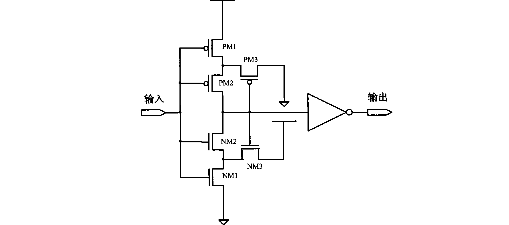
Since there are two transistors in series on the pull-up and pull-down paths of this Schmitt trigger, it is slower and takes up more chip area

Method used


Image

  • Dynamic body bias Schmitt trigger circuit
  • Dynamic body bias Schmitt trigger circuit
  • Dynamic body bias Schmitt trigger circuit

Examples


Embodiment Construction

[0015] The threshold voltage of the transistor is V T , when the source-to-body voltage V SB When ≠0, there are:

[0016] V T = V T 0 + γ ( | 2 φ F | + | V SB | - | 2 φ F | )

[0017] in γ = 2 q ϵ Si N Sub C ox , is the volume threshold factor; V T0 for V ...


PUM


Abstract

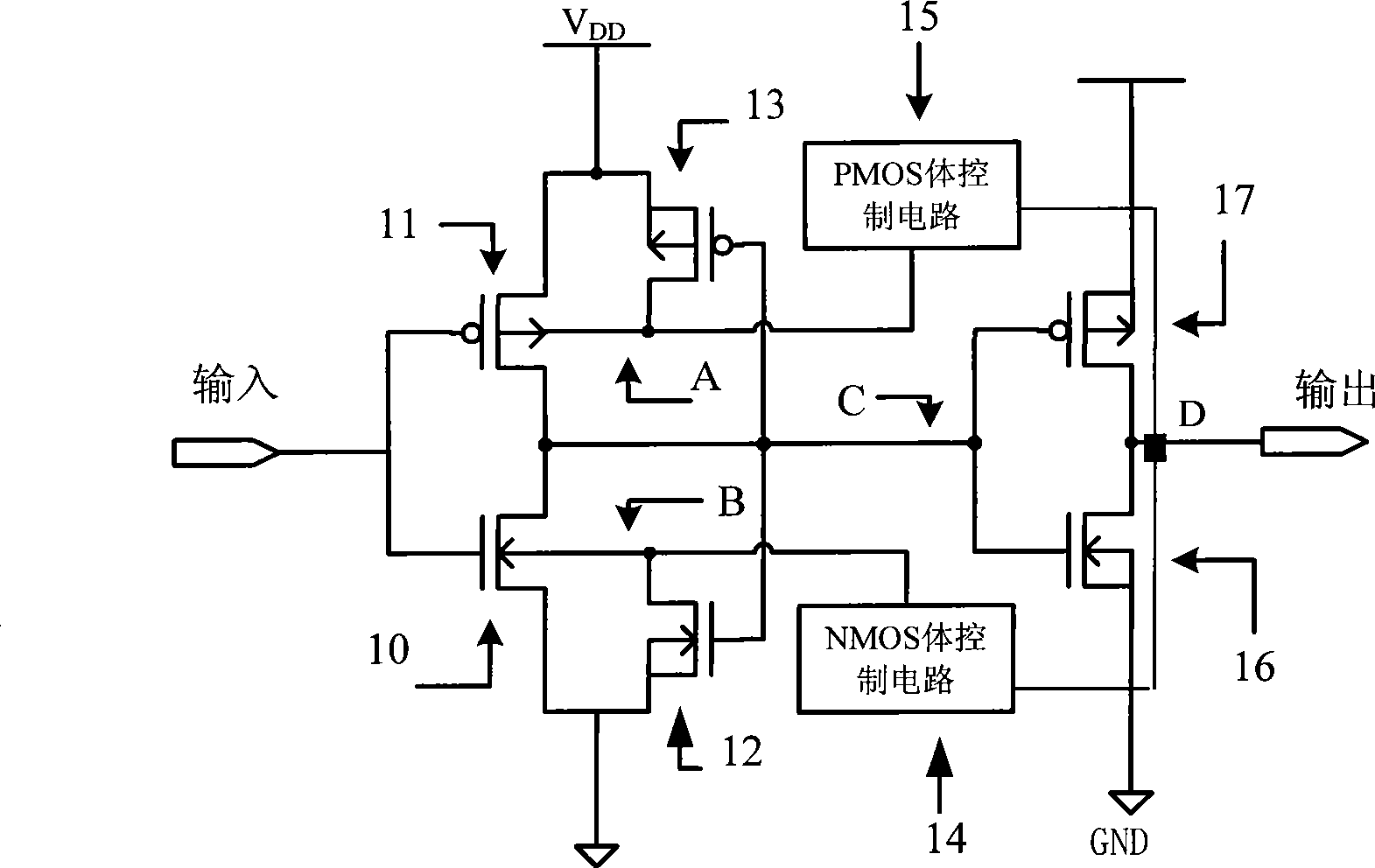
The invention discloses a dynamic body-bias Schmitt trigger circuit which utilizes a body-bias technique to control the body-area voltages of a first NMOS transistor (10), a first PMOS transistor (11), change the threshold voltages of the first NMOS transistor (10) and the first PMOS transistor (11) and further form the Schmitt trigger circuit with a double-switching threshold value. When an input signal is a lower electric level, under the action of a second NMOS transistor (12), a second PMOS transistor (13), an NMOS body control circuit (14) and a PMOS (15) control circuit, a Schmitt trigger presents a high switching threshold value V+; and similarly, when an input signal is a higher electric level, under the action of the second NMOS transistor (12), the second PMOS transistor (13), the NMOS body control circuit (14) and the PMOS (15) control circuit, the Schmitt trigger presents a low switching threshold value V-.

Description

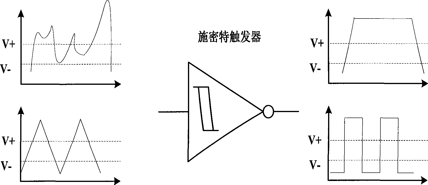
technical field [0001] The invention relates to a semiconductor integrated circuit, in particular to a Schmitt trigger circuit with double switching thresholds. Background technique [0002] A Schmitt trigger exhibits a hysteresis characteristic in its DC characteristic - there are different switching thresholds for different flipping directions. When the input signal changes from low level to high level, the switching threshold is V+; when the input signal changes from high level to low level, the switching threshold is V—. Schmitt triggers are widely used in digital circuits and analog circuits, especially in anti-noise and waveform shaping, Schmitt triggers play an irreplaceable role. [0003] When the input low-level signal of the Schmitt trigger is coupled with noise, as long as the superposition of the signal level and the noise level does not exceed V+, the output state of the Schmitt trigger will not change; the input high-level signal When there is noise coupled, ...

Claims


Application Information

Patent Timeline
Patent Type & Authority Applications(China)
IPC IPC(8): H03K3/3565
Inventor 苏强吴龙胜刘文平汪西虎
Owner CHINA AEROSPACE TIMES ELECTRONICS CORP NO 771 RES INST
Why Eureka
Try Eureka